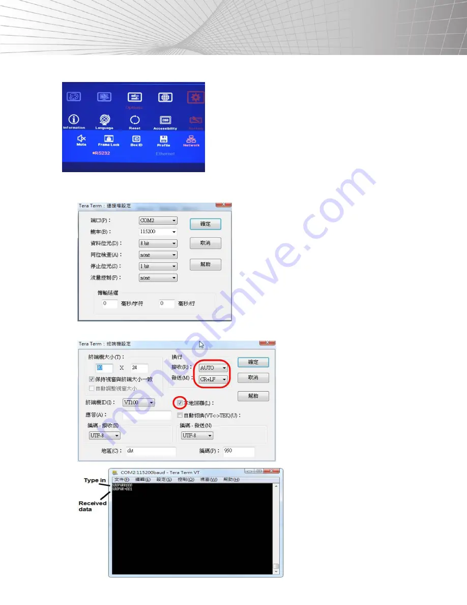
Shinybow USA SB-3403 Скачать руководство пользователя страница 49

47

SETTINGS

5. [NETWORK]

• 

RS-232 can only be used under this menu.

• 

Users can use external UART to Ethernet converters to control the SB-
3403 through the Ethernet control system.

• 

Users can use a simple button type RS-232 controller to switch among 

the different Profile settings.

RS-232 Setting:

a. Serial Port Setup

b. Terminal Setup

Содержание SB-3403

Страница 1: ...SB 3403 4TV VIDEO WALL CONTROL BOX INSTRUCTION MANUAL ...

Страница 2: ...ion 12 This unit should be installed in a cool dry place away from sources of excessive heat vibration dust moisture and cold Do not use the unit near stoves heat registers radiators or other heat producing devices 13 Do not block fan intake or exhaust ports Do not operate equipment on a surface or in an environment which may impede the normal flow of air around the unit such as a bed rug carpet o...

Страница 3: ...sons To prevent fire or shock hazard do not expose the unit to rain moisture or install this product near water Never spill liquid of any kind on or into this product Never push an object of any kind into this product through any openings or empty slots in the unit as you may damage parts inside the unit Do not attach the power supply cabling to building surfaces Use only the supplied power supply...

Страница 4: ...et the IR receiver to a position that can be accessed 3 Turn all Dip Switch pins on the Main Input to the OFF position to switch the authority of the system control to the OSD setting If any of the Main Input Dip Switches are turned to the ON position the Dip Switch setting command will be the 1st priority to execute if the OSD setting is conflicting with the Dip Switch setting 4 Apply the input s...

Страница 5: ...the video wall is created users can use the Ratio and Position functions to adjust the aspect ratio and final image position freely 5 Please note that the dimensions in coordinate system should have a 16 9 ratio 382 5 215 2 16 9 6 In the above drawing the coordinates for TV1 and TV2 are as follows TV1 coordinates for Top Left corner 0 586 Top Right corner 366 216 TV2 coordinate for Top Left corner...

Страница 6: ...an use the Overlap menu to align the position amongst the different SB 3403 s c Usually one full HD video can be applied to a video wall up to 6 x 3 5M if the watching distance is more than 3 meters 3mm pixel pitch If the watching distance is 2 meters the suitable video wall size is about 4 x 2 3M about 2mm pixel pitch 12 Portrait Display Mode If the display is at the portrait position users can a...

Страница 7: ...NGE AND POSITION SHIFT ACROSS ENTIRE VIDEO WALL 1 Users can change the entire video wall image 4 LCD s aspect ratio from 25 to 200 at both horizontal and vertical directions through the OSD and save with the Manual Mode Mode 2 This function allows users to select different modes to display the contents on the screen from different signal sources and still maintain required aspect ratio without dis...

Страница 8: ...e aspect ratio control across the entire video wall This function can allow users to use any signal content from non PC based devices and still keep the required aspect ratio without distortion Integrated with the function for the entire image 4 LCD s position shift without changing aspect ratio 4K2K HDMI loop out port for monitoring and daisy chain connections Programmable EDID to optimize video ...

Страница 9: ...ultiple units to build one true 4K2K video wall Each display unit location can be adjusted up to _900 pixels in all directions for image mapping Custom display modes created by user with LCD at any position and angle Looping playback for custom modes Image shift for LCD burn in mark protection PiP and PoP PiP up to 1024x768 at selectable locations with selectable aspect ratio and input source PoP ...

Страница 10: ...u again 6 Image Setup menu will not be activated if the input source is not from VGA 7 Once finishing one video wall setting users can apply the same setting value to the next project with the same configuration The GPM PC tool can backup the setting or install the same setting to other units 8 If using different aspect ratio LCD s but not 16 9 customized factory settings are required 9 Poor cable...

Страница 11: ... ratio if necessary f Adjust image position if necessary after aspect ratio change g The above sequence can be changed User can select Top Left then select Index or output port TV1 TV4 to key in coordinates It is not necessary to exit from OSD menu again 3 To adjust image position at H V without changing image size 4 Manual mode setting OSD main menu 5 Video wall main menu 6 Top Left coordinate me...

Страница 12: ...40 LCD 42 LCD 47 LCD 50 LCD 55 LCD 60 LCD 65 LCD 3 5mm 0 289280 0 514177 2 35 2 86 2 99 3 31 3 50 3 81 4 14 4 46 4 9mm 0 471163 0 837464 3 64 4 47 4 68 5 20 5 51 6 03 6 56 7 08 1 50 1 496090 2 552533 10 68 13 28 13 93 15 55 16 52 18 14 19 77 21 39 Active to Active Gap 0 3mm 3 8mm Bezel to Bezel 3 5mm 2 25mm Left Top 1 25mm Right Bottom 4 Types of Bezel Compensation a No bezel correction no informa...

Страница 13: ... 3 Top Right 34 Bottom Left 5 Bottom Right 4 Center up 35 Center 00 Center Down 45 NOTE 1 After the Dip Switch selection users need to Power OFF ON the unit again to implement the settings 2 Users can continuously adjust the PiP size and location via the remote control 3 Please adjust the aspect ratio of the PoP image under Image Properties Scaling 4 Entire video wall dynamic aspect ratio changes ...

Страница 14: ...FF no correction Bezel ON 3 5mm bezel to bezel MODE 04A 1X4 Bezel OFF no correction Bezel ON 3 5mm bezel to bezel Please apply 90 signal source or rotate image at 90 to get normal viewing angle MODE 05 4X1 RATIO 2 25 Bezel OFF 4 9mm bezel to bezel Bezel ON 1 5 bezel correction MODE 00 DUPLICATE MODE 4 displays show the same full screen content as video source MODE 01 2X2 RATIO 16 9 Bezel OFF no co...

Страница 15: ...WITH CLOCKWISE 15 ROTATION RATIO 1 7 Bezel OFF no correction Bezel ON 3 5mm bezel to bezel MODE 05A 4X1 RATIO 2 25 Bezel OFF 4 9mm bezel to bezel Bezel ON 1 5 bezel correction Please apply 90 signal source or rotate image at 90 to get normal viewing angle MODE 06 3X1 RATIO 1 69 4 output will show full screen image Bezel OFF no correction Bezel ON 3 5mm bezel to bezel MODE 06A 1X3 RATIO 1 69 Bezel ...

Страница 16: ...X2 WITH TV3 TV4 RIGHT SHIFT 1 2 PANEL WIDTH RATIO 2 22 Bezel OFF 4 9mm bezel to bezel Bezel ON 1 5 bezel correction MODE 14 2X2 WITH CLOCKWISE 15 ROTATION RATIO 1 7 Bezel OFF 4 9mm bezel to bezel Bezel ON 1 5 bezel correction MODE 15 2X2 WITH CLOCKWISE 15 ROTATION AND TV1 TV2 AT UPSIDE DOWN POSITION RATIO 1 7 Bezel OFF no correction Bezel ON 1 5 bezel correction MODE 16 2X2 WITH TV2 TV4 SHIFT DOWN...

Страница 17: ...ection MODE 56 TV4 DOWN SHIFT 1 4 PANEL HEIGHT RATIO 1 8 Bezel OFF no correction Bezel ON 3 5mm bezel to bezel MODE 26 RATIO 1 89 Bezel OFF no correction Bezel ON 3 5mm bezel to bezel MODE 34 RATIO 1 89 Bezel OFF 4 9mm bezel to bezel Bezel ON 1 5 bezel correction MODE 35 RATIO 5 33 FOR 3X3 APPLICATION Bezel OFF no correction Bezel ON 3 5mm bezel to bezel MODE 36 RATIO 5 33 FOR 3X3 APPLICATION Beze...

Страница 18: ...1 33 Bezel OFF no correction Bezel ON 3 5mm bezel to bezel MODE 123 TV4 DOWN SHIFT WITH 1 4 PANEL HEIGHT RATIO 1 8 Bezel OFF 4 9mm bezel to bezel Bezel ON 1 5 bezel correction MODE 124 75 COUNTERCLOCKWISE ROTATION RATIO 1 77 4 output will show full screen image Bezel OFF no correction Bezel ON 3 5mm bezel to bezel MODE 125 75 COUNTERCLOCKWISE ROTATION RATIO 1 77 4 displays show the same full scree...

Страница 19: ... 1 Bezel OFF 4 9mm bezel to bezel Bezel ON 1 5 bezel correction MODE 136 45 CLOCKWISE ROTATION RATIO 1 33 Bezel OFF 4 9mm bezel to bezel Bezel ON 1 5 bezel correction MODE 145 RATIO 1 Bezel OFF 4 9mm bezel to bezel Bezel ON 1 5 bezel correction MODE 146 RATIO 1 Bezel OFF no correction Bezel ON 3 5mm bezel to bezel ...

Страница 20: ...cted to 3 LCD SB 3403 TV4 output will show full screen content for system monitoring EXAMPLE THREE Mode 06A 1x3 Ratio 1 69 Please apply a 90 rotation to the image content to get the normal viewing angle If the content is not at a 90 rotation then the user needs to create a custom mode or rotate the image in the Orientation menu setting 1 Mode 06A means Dip Switch pin 6 should be set to the ON UP p...

Страница 21: ... EXAMPLE FOR INPUT RESOLUTION SETTINGS a When using a single SB 3403 please apply the 1920x1080 60Hz input resolution b For dual SB 3403 s in horizontal cascade please set to 3840x1080 60Hz as the input resolution c For dual SB 3403 s in vertical cascade please set to 1920x2160 60Hz as the input resolution d For 2x2 4 SB 3403 cascaded 3840x2160 30Hz input resolution will get the best video quality...

Страница 22: ... Bezel compensation on the Dip Switch 6 If PiP is required select the Dip Switch in the PiP Input PiP Mode and PiP Size Location After finishing the Dip Switch settings Power OFF and ON the unit again to execute the commands in Dip Switch settings on the SB 3403 PRESET MODE MODE 00 1 Select the Main Input Dip Switch 2 All Dip Switch pins in the Display Mode are set to the OFF position 3 All output...

Страница 23: ...PiP Mode to the PoP Full position users will get a full screen PoP image 7 Users can select the PoP Raw to keep the original aspect ratio of two contents 8 Power OFF ON the system again PRESET MODE MODE 00 1 Install the TV as showed in the picture 2 Select the Main Input Dip Switch 3 The Display Mode Dip Switch 3 is set at the ON position 4 Connect the SB 3403 outputs to the related LCD s a TV1 to...

Страница 24: ...3403 if the signal source is 4K content applying 3840x2160 30Hz input resolution will get the best video quality If FHD content please apply the FHD input resolution b For dual SB 3403 s horizontal cascading 3840x1080 60Hz will get the best video quality c For 2x2 4 SB 3403 cascading 3840x2160 30Hz input resolution will get the best video quality d For more complicated cascading please follow the ...

Страница 25: ...1 V 2 H 1 V 3 Overlap Bottom Top BTM Top d Signal source should be connected to all of the SB 3403 through daisy chaining the connections e Set overlap pixels to fine tune the image position among each of the SB 3403 if necessary f During Overlap adjustment the image may have a frame tear It will disappear after powering the unit ON again g Save the final settings to the OSD Options Settings Profi...

Страница 26: ... s coming closer until the image edges meet together d During Overlap adjustment the image may have a frame tear It will disappear after powering the unit ON again e Save the final settings to the OSD Options Settings Profile Save Index 1 5 Users can recall it at any time NOTE 1 During the Overlap adjustment the image may have frame tear because the parameters are just temporarily stored in the sy...

Страница 27: ...fferent displays one content or dual contents on the video wall Users can use the PiP PoP function to add more display content in each display zone In this case the maximum display content will be up to 4 in the above video wall EXAMPLES FOR CASCADED DISPLAYS 4 x Mode 45 46 Recommended Signal Source Resolution 3840x2160 2 x Mode 145 146 Recommended Signal Source Resolution 3840x1080 2 x Mode 126 1...

Страница 28: ...he settings from the OSD or the setting saved in the Profile 3 After finishing the OSD operations please save the OSD settings into the Profile Index for long term reservation 4 The IR remote control has a Shortcut key for the Profile Index loading function see below Users needs to use the IR remote control to access the IR receiver on front panel or the IR extender connected to the port on the ba...

Страница 29: ...es horizontal position d Vertical Position Adjusts manually the images vertical position e When the input is a VGA signal please connect the signal to the SB 3403 then turn on the SB 3403 for image position auto alignment After this process unless the user applies other VGA input signals the SB 3403 will not do auto alignment again to avoid image shift IMAGE PROPERTIES Image properties is designed...

Страница 30: ...r the main PiP image can be the same or swapped The location of the PiP image can be controlled by the OSD menu at any location inside the main image The size of the PiP image is also flexible and can be controlled by the OSD menu as well Both the main and PiP image will go through high end 3D motion de interlacing 5 SUB MENUS UNDER THE PIP SETTING MENU Display Enables the PiP or PoP Size Sets the...

Страница 31: ...ing under the Image Properties OSD menu Source Users can select the input source for the PiP PoP image from all the input ports By selecting different input ports for the Main PiP PoP images users can have different combinations of displays Users can save different settings into the Profile under the Option menu and recall it at any time IMAGE ORIENTATION This image orientation function will be ap...

Страница 32: ... display mode the mode will show up at the bottom of the OSD Users can set the same display mode with the Dip Switch to get the same display mode MANUAL MODE The purpose for the Manual Mode is to let the user create any type of display mode they want Here is the structure and concept Users can create 10 different display modes and save in the Index 1 10 Each Index consists of up to 4 LCD s TV1 TV4...

Страница 33: ...e and display angle settings 4 Reset will reset the coordinates to the default settings in the current TV setting 5 Users can manually input the coordinates for the Top Left and Top Right corners through the OSD menu direction keys GAlign PC tool is also available to input the coordinates for 4 LCD s TV1 TV4 The user needs to connect to a PC with the SB 3403 through the RS 232 port on back panel A...

Страница 34: ...an easily Zoom In enlarge the image by reducing the image capture range If the user wants to increase the capture range Zoom Out it depends on how many image pixels are in image borders Sometimes it is limited to only few lines 1 Ratio Menu 3 Options Ratio Position Reset 2 4 menus can work at the same time 5 Horizontal Ratio adjustment 1 This function can execute the Image Zoom In Out to change th...

Страница 35: ...al Ratio 3 No image shift is possible if the Horizontal Ratio doesn t change 4 This function will apply to the entire video wall NOTE The position shifting range is as following a Maximum shift range is inside the input video content b If the image is at ZOOM IN 200 the image can be shifted up to the video walls center line half image will be missing See below c If the image is at ZOOM OUT 25 the ...

Страница 36: ... 2 product B in Index 3 product C in Index 4 and product D in Index 5 After setting the looping playback the user will see advertisements for the complete image then highlight each product on a specific LCD in sequential order b Users can select the playback modes Index and time interval from the OSD c Users can input 2 of the same Indexes to double the display interval time for this Index d Pleas...

Страница 37: ...for the looping playback in Loop Range 2 If 3 is selected then only Index 1 Index 2 and Index 3 can be selected for the looping playback 1 The time interval to switch among different Indexes can be set by the Loop Time 2 The max looping time interval is 10 minutes 600 seconds 3 Users can create a different Index to highlight different products from the same input source ...

Страница 38: ...hysical design drawings into 1920x1080 coordinates and pick up the coordinates at the Top Left and Top Right corners in each LCD s active display region then input them to the SB 3403 through the OSD or PC tool to get the result The original point for the coordinate system is set at the Top Left corner as 0 0 b Please note that the coordinate system 16 9 in the H V directions should have the same ...

Страница 39: ...ons then collect the Top Left and Top Right coordinates Use Microsoft Picture Manager to trim the edges of the display area or directly use the Paint software to trim the image Resize to 1920x1080 image resolution in JPG or PNG formats To view this photo file in Microsoft Paint the user can mouse click to capture the coordinates Adobe PhotoShop can also be used to capture the coordinates Example 6...

Страница 40: ... upload coordinates 5 Uploading coordinates via the GAlign PC tool Above is PC tool GAlign for users to load coordinates of each LCD through the RS 232 port Please select Index and press Write after keying in all the coordinates This is more convenient for users that are not able to see the OSD for manual upload The results will be the same as manual upload via the OSD Users can also set the H V a...

Страница 41: ...user needs to split the image into several sections in the FHD size to cover the LCD display range in each of the SB 3403 s After finishing the assignments the user needs to do further Video Wall settings to split the signal source for each SB 3403 ZOOM assign the image location PAN and adjust the image positions OVERLAP so that the adjacent SB 3403 image can match together All of the operations c...

Страница 42: ... second corner the image position and size will be also change to show the new image in 16 9 aspect ratio e OSD Position next to the Top Right coordinate input menu can adjust the image position for each LCD in the H V directions without changing the rotation angle and size of the image It is convenient for position fine tuning adjustment f Users need to save the settings into the Option Settings ...

Страница 43: ...403 Example A 3x1 SB 3403 Horizontal Cascade Horizontal Zoom 3 Vertical zoom 1 Example B In a 3x3 SB 3403 Cascade Horizontal Zoom 3 Vertical Zoom 3 PAN LOCATION SELECTION Pan is to assign the split image location for each Display Unit Horizontal value is calculated from the LH to RH direction and Vertical value is calculated from top to bottom Users need to set the H V Pan value to assign the imag...

Страница 44: ... multiple SB 3403 cascade applications the Overlap value in each SB 3403 should be the same so that all images have the same scaling factor Users can use the Overlap adjustment to change the aspect ratio in the video wall image as well Example for 2 SB 3403 cascade Overlapping pixels for the Zone A Display Unit A B Display Unit B should be the same Users can set the Zoom Pan open the Overlap menu ...

Страница 45: ...put Mode Network status Model Name and Firmware version LANGUAGE OSD Language 3 OSD menu languages can be selected English Simplified Chinese and Traditional Chinese RESET 2 types of Resets can be done Reset All Reset Video Wall Reset All will reset all the users settings but the settings stored in the Index under Manual Mode and Profile will not be deleted Reset Video Wall will reset the settings...

Страница 46: ... OSD Menu Time Out The OSD menu will disappear from the screen based on the time settings The default time is 30 seconds OSD Time Out shortcut key is available on the IR remote control When Off is selected the OSD menu will remain on the screen until the user activates the other OSD functions or the input output mode changes 3 LOGO TIME OUT Sets the time to show the Splash screen If zero is select...

Страница 47: ...rofile settings Network Sets the RS 232 and network control 1 AUDIO MUTE Mute Off Will enable the audio output Mute On Will disable the audio output Mute Remote control hot key is available 2 FRAME LOCK AND FREE RUN MODE Frame Lock will ensure the input and output frame rate synchronize together This is mainly for multiple SB 3403 applications If Frame Lock is disabled the system will be in Free R...

Страница 48: ...how the cascaded images with a single content across whole video wall 2 To show 2 side by side contents across whole video wall 3 To show 1 PiP content as a cascaded image 4 To show 2 PiP contents as a cascaded image Users can save these different display patterns on the SB 3403 and recall them with the RS 232 or remote control PLEASE NOTE When executing the system reset the Profile settings will ...

Страница 49: ... Users can use external UART to Ethernet converters to control the SB 3403 through the Ethernet control system Users can use a simple button type RS 232 controller to switch among the different Profile settings RS 232 Setting a Serial Port Setup b Terminal Setup ...

Страница 50: ...input signal resolutions b Different PC display cards have different settings and behaviors Many users may not be able to establish the correct settings c High end media players or servers can support a large range of outputs from 720p to 4K2K If there is not an EDID selection function only one default EDID can be selected by the media player The system may not show the best video wall output qual...

Страница 51: ...d show different results If this happens please open the PC resolution settings window and select the desired output resolution from the PC Users can choose the PC output resolution up to the maximum resolution set by the EDID on the SB 3403 If the users want to a create custom output resolution on the PC please select Reduced Blanking timing in the high resolution output to reduce the output cloc...

Страница 52: ...s 6 Open the GAlign exe file to see the operation window 7 This PC tool is an exe file and may be blocked by Anti virus software Please remove this barrier GALIGN PC TOOL OPERATION PROCEDURES 1 Open the GAlign exe file Select a Language 2 Users should see COM at the top right corner If not the RS 232 is not connected to the PC Please check the Device Manager on the PC and make sure the RS 232 USB ...

Страница 53: ...o position can be shifted before the user adjusts the Warp Ratio 12 Profile is to save all settings on the SB 3403 including the input source PiP PoP video wall settings ratio looping playback color Please select the Profile and click Save to store the setting and click Load to recall it at any time A maximum of up to 5 profiles can be saved Don t forget to press Write before saving the settings t...

Страница 54: ...nited States ofAmerica SHINYBOWUSA makes no representation that materials pertaining to the product are appropriate or available for use in other locations other than the shipping address you provided with respect thereto You are advised that the product may be subject to U S export controls DISCLAIMERS AND LIMITATION OF LIABILITY SHINYBOWUSA may change or modify the product at any time from time ...

Страница 55: ...THIS PAGE IS INTENTIONALLY LEFT BLANK ...

Страница 56: ...122 Rose Ln Suite 303 Frisco Texas 75034 1 877 SHINY USA 1 877 744 6987 1 972 377 2508 sales shinybowusa com www shinybowusa com ...

Отзывы: