3(65)
Contents
1.
General Description .................................................................................. 9
1.1
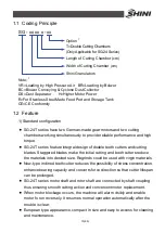
Coding Principle ................................................................................. 10
1.2
Feature............................................................................................... 10
1.3
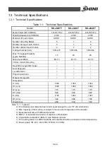
Technical Specifications..................................................................... 12
1.3.1
Technical Specifications .......................................................... 12
1.3.2
Dimensions.............................................................................. 13
1.4
Safety Regulations ............................................................................. 13
1.4.1
Safety Signs and Labels .......................................................... 13
1.4.2
Transportation and Storage of the Machine............................. 15
1.5
Exemption Clause .............................................................................. 17
2.
Structural Features and Working Principle ........................................... 18
2.1
General Description ........................................................................... 18
2.1.1
Working Principle..................................................................... 18
2.2
Safety System.................................................................................... 18
2.2.1
Emergency Stop ...................................................................... 19
2.2.2
Safety Switch........................................................................... 20
2.2.3
Gate Lock ................................................................................ 20
2.3
Assembly Drawing ............................................................................. 21
2.3.1
System Structure (SG-24T) ..................................................... 21
2.3.2
Parts List (SG-24T).................................................................. 22
2.3.3
Cutting Chamber and Blade Rest ............................................ 25
2.3.4
Cutting Chamber and Blade Rest Parts List ............................ 26
2.3.5
Transmission ........................................................................... 27
2.3.6
Feed Box, Feed Port and Material Stopper ............................. 28
2.3.7
Feed Box, Feed Port and Material Stopper Parts List.............. 28
2.3.8
Storage Bin.............................................................................. 28
2.3.9
Storage Bin Parts List .............................................................. 28
2.4
Electrical Diagram .............................................................................. 29
2.4.1
Main Circuit (400V).................................................................. 29
2.4.2
Control Circuit (400V) .............................................................. 30
2.4.3
Electrical Components Layout (400V) ..................................... 31
Содержание SG-24T
Страница 1: ...SG 24T Screenless Granulator Date Apr 2013 Version Ver B English...
Страница 2: ......
Страница 8: ...8 65...
Страница 25: ...25 65 2 3 3 Cutting Chamber and Blade Rest Picture 2 5 Cutting Chamber and Blade Rest...
Страница 29: ...29 65 2 4 Electrical Diagram 2 4 1 Main Circuit 400V Picture 2 9 Main Circuit 400V...
Страница 30: ...30 65 2 4 2 Control Circuit 400V Picture 2 10 Control Circuit 400V...
Страница 31: ...31 65 2 4 3 Electrical Components Layout 400V Picture 2 11 Electrical Components Layout 400V...
Страница 34: ...34 65 2 4 5 Main Circuit 230V Picture 2 12 Main Circuit 230V...
Страница 35: ...35 65 2 4 6 Control Circuit 230V Picture 2 13 Control Circuit 230V...
Страница 36: ...36 65 2 4 7 Electrical Components Layout 230V Picture 2 14 Electrical Components Layout 230V...
Страница 40: ...40 65 2 5 4 Proportional Valves Picture 2 18 Control Cabinet and Valve...
Страница 55: ...55 65 2 seized up machine stops Notice Mount sensor and ensure its space with big wheel to about 2 4mm...


