48(65)
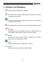
Caution!
In order to avoid personal injury and machine damage, the lockup screws
has to be tightened.
3.6 Installation of Feed Box, Feed Port and Storage Bin
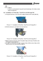
1) Lift up the feed box to fix it onto the cutting chamber with screws (M8
×
35).
Picture 3-11: Installation of Feed Box, Feed Port and Storage Bin 1
2) Hold the feed port, and insert it into the feed box.
Picture 3-12: Installation of Feed Box, Feed Port and Storage Bin 2
3) Before fixing the feed port, place the plastic strips at the top of feed box and
let feed port press against it.
4) Lay down the feed port and align its screw holes with the screw holes on the
feed box, then lock the screws up (M8
×
20).
Picture 3-13: Installation of Feed Box, Feed Port and Storage Bin 3
Содержание SG-24T
Страница 1: ...SG 24T Screenless Granulator Date Apr 2013 Version Ver B English...
Страница 2: ......
Страница 8: ...8 65...
Страница 25: ...25 65 2 3 3 Cutting Chamber and Blade Rest Picture 2 5 Cutting Chamber and Blade Rest...
Страница 29: ...29 65 2 4 Electrical Diagram 2 4 1 Main Circuit 400V Picture 2 9 Main Circuit 400V...
Страница 30: ...30 65 2 4 2 Control Circuit 400V Picture 2 10 Control Circuit 400V...
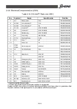
Страница 31: ...31 65 2 4 3 Electrical Components Layout 400V Picture 2 11 Electrical Components Layout 400V...
Страница 34: ...34 65 2 4 5 Main Circuit 230V Picture 2 12 Main Circuit 230V...
Страница 35: ...35 65 2 4 6 Control Circuit 230V Picture 2 13 Control Circuit 230V...
Страница 36: ...36 65 2 4 7 Electrical Components Layout 230V Picture 2 14 Electrical Components Layout 230V...
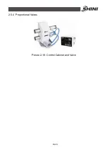
Страница 40: ...40 65 2 5 4 Proportional Valves Picture 2 18 Control Cabinet and Valve...
Страница 55: ...55 65 2 seized up machine stops Notice Mount sensor and ensure its space with big wheel to about 2 4mm...


