


Operation Instructions for ZLP250
Temporarily Installed Suspended Access Equipment
5
rope locking system will start to work and will make the locking block is locked on
the safety wire rope. The suspended platform will stop lowering.
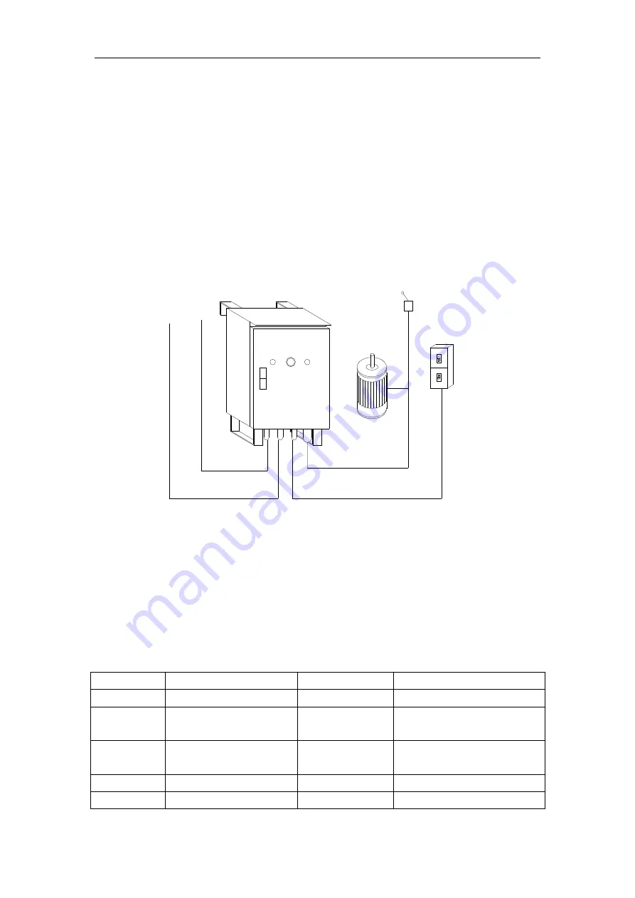
3.5 Electric Control System
The electric control box is used to control the working of the suspended platform. The main
components are installed on the insulation board. On the box door, there is power indicator light,
start button, emergency stop button. On the bottom of the electric box, there is power supply,
handle switch, power board and the hoist connection plug.
(See figure 6 as below).
1
2
3
4
5
6
7
8
图9 电气箱示意图
Figure 5: Electric Control System
The electric control box is used for the control of the up and down movement of
the suspended platform. The main elements are mounted onto an isolated plate and the
universal switch, power indicator light, starting button and emergency stop button are
fixed on the panel.
3.5.1
The schematic diagram and wiring diagram see attached figure 4 and attached 5.
3.5.2
The main electric elements see table 3 next page.
Table 3: List of Electric Elements
Code
Name
Code
Name
KM1,2,3
AC contactor
HL
Power indicator light
QF1
Power leakage breaker
SL1
Limit switch
(or travel switch)
QF2
Miniature
circuit
breaker
XPI
10-core plug
TC
Control transformer
XP2
5-core plug
FR
Thermal overload relay HA
Alarm bell