


Operation Instructions for ZLP250
Temporarily Installed Suspended Access Equipment
1
1.
Brief Description
ZLP series temporarily installed suspended access equipment is ideal equipment
for building facade construction, decoration, cleaning and maintenance. And it is also
widely used in façade building, glass cleaning and installing, elevator installing, ship
building and repairing, or in other works such as big-size tank, bridge, embankment
and chimney.
It is easy for operation, flexible for moving, reliable in safety. Besides, it is not
necessary to build scaffolding in the construction, the efficiency will be promoted and
the cost will be reduced.
Therefore, ZLP series versatile knock-down platforms
provides workers safer, easier and more efficient platform access.
ZLP series temporarily installed suspended access equipments conform to the
national standard GB19155-2003.
2.
Main Parameters
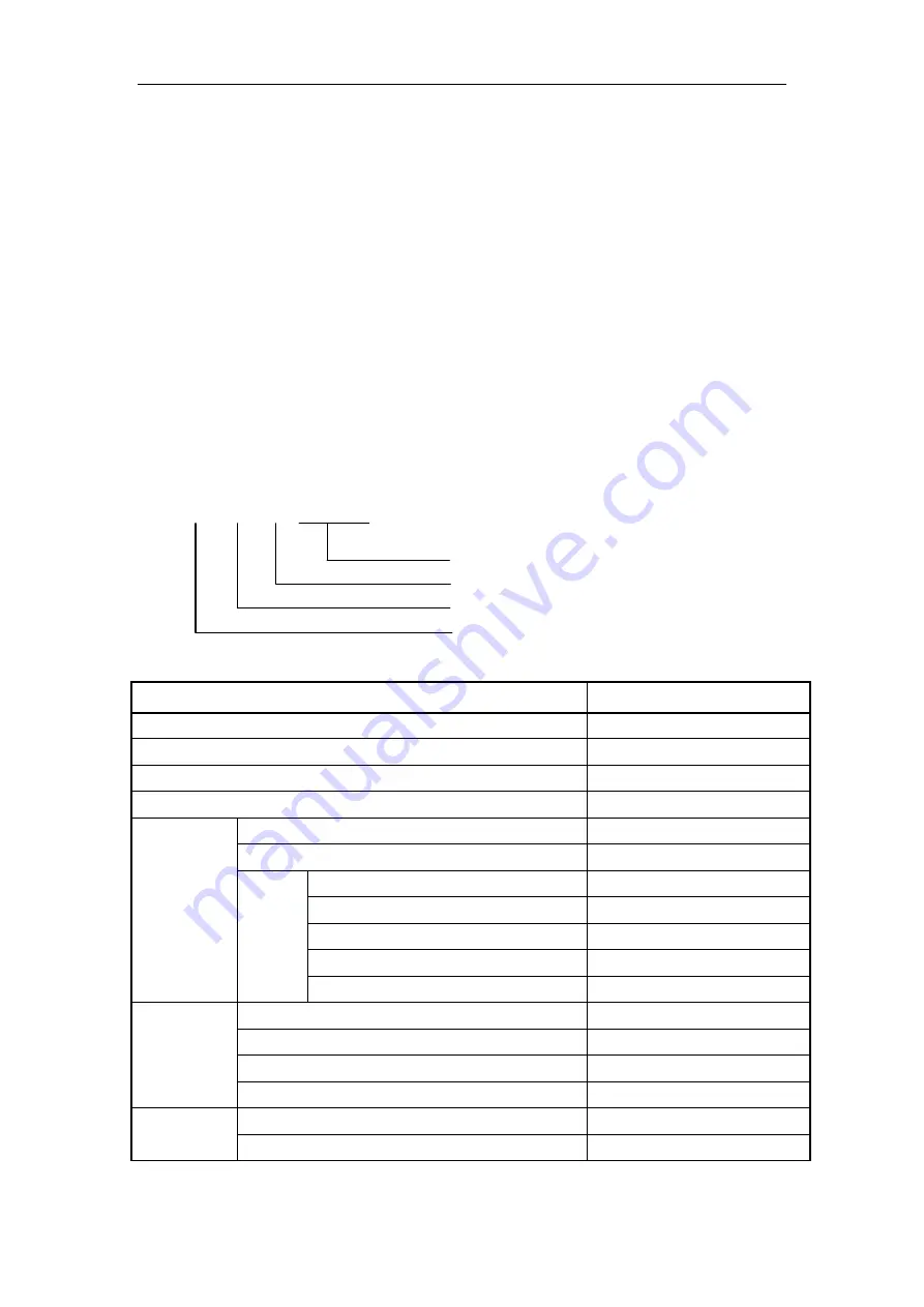
Model description
Z L P 250
Main parameter or rated capacity (kg)
Identity Symbol: P --- Climb Type
Suspended Platform
Decoration machinery
Table 1: Main Parameters for ZLP250
Item
Parameters
Rated capacity
250kg
Rated speed
8-10 m/min
Platform length
1.2m
Steel rope
4
Χ
31SW+Fc-8.3
Hoist
Hoist model
LTD6.3
Rated lifting force
6.3KN
Motor
Model
YEJ90L-4
Power
1.5 KW
Voltage
AC380V
Speed
1420 r/m
Brake force moment
15 Nm
Safety lock
Configuration
Centrifugal type
Permission force of impact
30 KN
Locking Cable Distance
<
100mm
Locking Cable Speed
≥
22m/min
Suspension
mechanism
Front beam overhang
1.3m-1.5m
Height adjustment
1.27m -1.83 m