Shenxi ZLP250 Скачать руководство пользователя страница 11

Operation Instructions for ZLP250


Temporarily Installed Suspended Access Equipment 

  9 

4.5.2

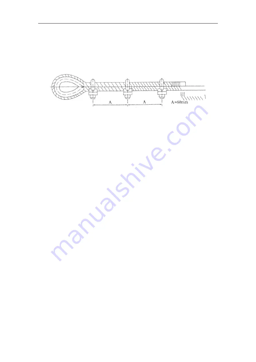
  The  fixing  method  at  the  end  of  steel  rope  should  be  in  accordance  with  the 

requirements  of  the  standard  GB5976-86  (see  figure  7  as  below).  U  bolt  is  fixed  on 
the  rear  portion  of  steel  ropes;  clamp  is  fixed  on  the  working  section  of  steel  ropes, 
which cannot be mixed up. The steel rope clamp cannot be alternately arranged on the 
steel rope, and the correct clamping method is as follows: 


Figure 7: The Correct Clamping Method


a.


Quantity of the clamps: 3 pieces (at least); 

b.


Arrangement of the clamps (see figure 9 above); 

c.


The distance between the clamps is 60 mm; 

d.


Tightening  of  the  clamp:  the  first  clamp  should  be  close  to  the  rope  ring  and 
tightened. Care must be taken that it is not allowed to damage the steel rope when 
tightening, and then make the second and third clamps. It is necessary to make the 
clamps tightened again after the steel rope is loaded one or two times. 

4.5.3

  Care  must  be  taken  that  the  steel  ropes  must  not  be  damaged,  deformed  or 

twisted. 

4.7.4

 The hoist must be fixed with the pins and bolts. 

4.7.5

 Make sure that the plugs of the motors and the control button be inserted into the 

sockets of the control box correctly. 

4.7.6 

The  power  supply,  connected  with  the  control  box,  should  have  the  null  and 

earth lines and the control box should be ground contacted reliably. 

4.7.7 

Make  sure  that  the  connection  of  the  steel  rope  with  the  hoist  is  in  normal, 

otherwise, stop connection for check. 

4.7.8

 The remaining steel rope should be placed in order and bounded well. 

4.7.9

 The four heavy hammers must be hung onto  the lower ends  of the safety steel 

rope respectively.


5.


Operation 

5.1 Checking and Adjusting after Installation 

5.1.1

  Check  if  the  connections  are  correct,  the  steel  ropes  are  not  damaged,  the 

clamping are correct, the nuts are tightened, the front beam overhang is in accordance 
with  the  standard.  Make  sure  that  the  moment  of  force  of  the  stability  of  the 
suspension mechanism is over two times of the overturning moment. 

5.1.2

 Check if the wiring is correct. The voltage of power should be within the range 

of  380V

5%.  After  the  power  is  connected,  push  the  testing  button  on  the  power 

leakage  breaker,  and  power  leakage  breaker  should  work  swiftly.  Close  the  door  of 

Содержание ZLP250

Страница 1: ...s Equipment OPERATION MANUAL For Shenxi ZLP250 Temporarily Installed Suspended Platform INSTALLATION OPERATION MAINTENANCE TEL 86 510 88215261 Fax 86 510 88700937 Website www shenxi com E mail shenxi...

Страница 2: ...llation 7 4 2 Installation of Suspension Mechanism 7 4 3 Installation of Hoists Safety Locks and Electric Control Box 8 4 4 Connection Between Suspended Platform and Suspension Mechanism 8 4 5 Special...

Страница 3: ...eries versatile knock down platforms provides workers safer easier and more efficient platform access ZLP series temporarily installed suspended access equipments conform to the national standard GB19...

Страница 4: ...ght Lifting part including hoist safety lock and electric control system Steel Platform 180kg Suspension mechanism 115kg Counter weight 400kg 3 Main Structure and Operation Principle 3 1Suspended Plat...

Страница 5: ...the tommy bar for fixing the reinforced steel rope and counter weight will be placed on the rear base For details of structure see attached figure 1 suspension mechanism Figure 2 Suspension Mechanism...

Страница 6: ...d to produce braking torque that stops and supports the suspended platform In the event of power failure or emergency the manual descending device can be used to prompt the suspended platform to slide...

Страница 7: ...nnection plug See figure 6 as below 1 2 3 4 5 6 7 8 9 Figure 5 Electric Control System The electric control box is used for the control of the up and down movement of the suspended platform The main e...

Страница 8: ...ing power supply platform stops Alarm bell rings If the upper limit switch bumps the limit block and works only after the suspended platform is lowered the start button and control button can be press...

Страница 9: ...Installation of Suspension Mechanism See attached figure 1 suspension mechanism and use the special installing tool pinch bar if necessary 4 2 1 Insert the tommy bars into the front base and rear bas...

Страница 10: ...2 Install safety lock on the bracket of the hoist mounting frame and tighten with bolts Fix the limit switch onto the right position of the safety lock 4 3 3 Install and hang the electric control box...

Страница 11: ...twisted 4 7 4 The hoist must be fixed with the pins and bolts 4 7 5 Make sure that the plugs of the motors and the control button be inserted into the sockets of the control box correctly 4 7 6 The p...

Страница 12: ...the suspended platform upward and downward 3 5 times for about 3 5 m travel and check a The noise of the hoist should be normal and the electromagnetic brake will be actuated reliably b Press emergenc...

Страница 13: ...f the suspension mechanism is over two times of the overturning moment 5 3 5 It is not suggested to install the platform over the rated length or use the two platforms together And it is also not allo...

Страница 14: ...the platform lowered smoothly onto the ground 5 3 14 Site environment a No high voltage line within the 10 meters b It is not allowed to use the equipment in thunderstorm fog or the wind of grade 5 wi...

Страница 15: ...tch to stop the moving of the platform replace the contactor or control button The electromagnetic brake is out of order 1 The space between the electromagnetic disk and the armature is too big 2 Too...

Страница 16: ...ge AC380 V and output voltage DC99 V Low voltage of the power supply Check and adjust the voltage Damage of hoist Check and repair the hoist Abnormal noise of the motor or the motor is hot Operation l...

Страница 17: ...on condition and the working period After the end of use of entire machine a thorough keeping and examination should be done 7 3 1 Hoist a Replace the oil in the gear reducer No 30 machine oil quantit...

Страница 18: ...Care must be taken that the bottom plate of the platform balustrades mount frame for hoist and the suspension mechanism should not be deformed when loading and transportation 9 Documents and Tool 9 1...

Страница 19: ...Operation Instructions for ZLP250 Temporarily Installed Suspended Access Equipment 20 Attached figure 1 Suspension Mechanism...

Страница 20: ...Operation Instructions for ZLP250 Temporarily Installed Suspended Access Equipment 21 Attached Figure 2 LTD6 3 Hoist Structural Diagram...

Страница 21: ...Operation Instructions for ZLP250 Temporarily Installed Suspended Access Equipment 22 Attached Figure 3 LTD6 3 Hoist Exploded View...

Страница 22: ...sc ZLP6308 1 11 1 29 Bearing 6005 2Z 1 8 Steel belt assembly ZLP6308 1 8 1 30 Worm ZLP6308 1 1 1 9 Bearing 16304 Z 1 31 Nut M8 4 10 Wire pressing unit 1 32 Pinion shaft ZLP6308 1 7 1 11 Cover ZLP6308...

Страница 23: ...ded Access Equipment 24 Attached Figure 4 Electric Wiring Diagram TX 15 SB3 10 L2 L1 380V 36V HL L3 N TC KM3 KM2 U 2U FR FU W5 V5 2V 2W M L7 KM1 L4 L8 L9 L5 L6 QF1 STP SB2 8 FR HA KM3 KM2 KM1 95 YB U...

Страница 24: ...tor 3 Armature See figure 10 Electromagnetic Brake of Motor 4 Rectifier module Junction box of Motor 5 Centrifugal speed limiter See attached figure 3 LTD6 3Hoist 6 Rope pressing unit See attached fig...

Страница 25: ...trol box Electric cable Location Indicating lamp of the power supply Suspended platform Connections Actuation of the universal switch Tube damaged or rust Actuation of the AC contactor Crack in weldin...

Отзывы: