


Operation Instructions for ZLP250
Temporarily Installed Suspended Access Equipment
4
3.3 Hoist
The hoist is the powered unit for the platform with the climbing structure.
3.3.1
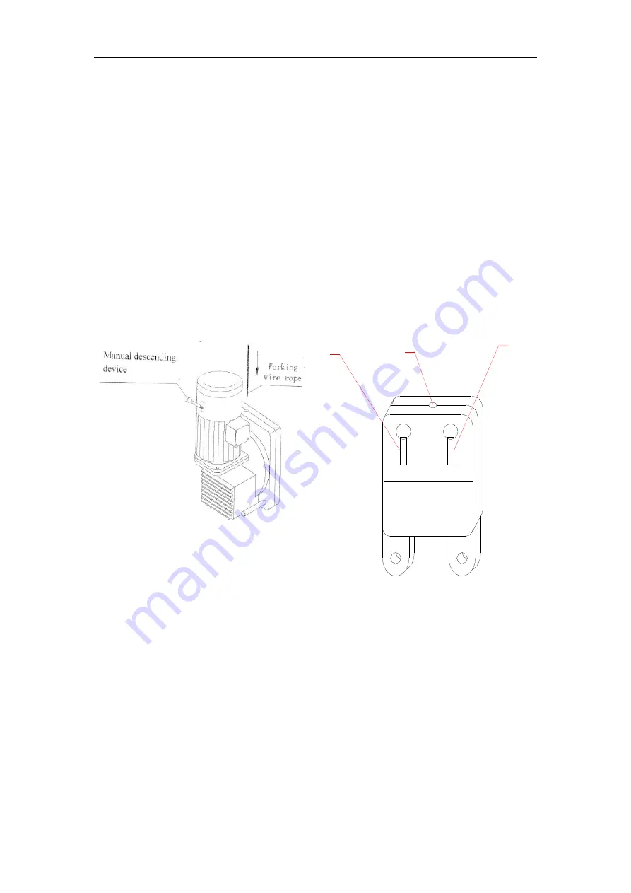
The hoist for ZLP250 is model LTD6.3. It consists of electromagnetic brake
motor, centrifugal speed limiter and dual speed reduction system and “α”
cable-guiding system (For details of structure, see attached figure 4 and attached
figure 5). The hoist is driven by the electromagnetic brake three-phase asynchronous
motor through the worm gear and a pair of reduced gears. The suspended platform
will be moved upward and downward with the movement of the hoist.
3.3.2
The hoist is provided with automatic rope feeding function and operators just
need to insert steel rope into the inlet of the hoist (see figure 3 as below).
3.3.3
The electromagnetic brake of hoist motor is able to be auto-engaged to produce
braking torque that stops and supports the suspended platform. In the event of power
failure or emergency, the manual descending device can be used to prompt the
suspended platform to slide downwards at even speed (see figure 3 as below).
Figure 3: LTD5 Hoist Figure 4: LSL30 Safety Lock
3.4 Safety Lock
The LSL30 safety lock is the safety-protecting device for the suspended platform.
When the working steel rope is broken suddenly, the safety lock will be actuated to
lock the safety steel rope to prevent the suspended platform from falling down.
The working principle: The safety wire rope goes through the rope inlet hole to
the space between the pressing wheel and the block rotation disc. When the platform
goes down, the steel wire rope drives the wheels to move in the opposite direction by
the friction power. There is block on the rotation disc. When the lowering speed is
over the regulated value, the centrifugal force of the block will overcome the pressing
force of the spring. Then the components will be touched and as a result , the wire
1
2
3
7