background image

Ref. No.

Part No.

Description

Code

Ref. No.

Part No.

Description

Code

VC-V50S
VC-V80T
VC-V91T

70

C6142

VCEAEM1CW336M V 33

16V Electrolytic

AB

(V91T)

C6143

VCEA9M1HW105M V 1

50V Electrolytic

AB

(V91T)

C6144

VCEA9A1CW226M V 22

16V Electrolytic

AB

(V91T)

C6145

VCEA9M1CW106M V 10

16V Electrolytic

AB

(V91T)

C6161

VCKYCY1EF104Z

V 0.1

25V Ceramic

AA

(V91T)

C6162

VCEA9M1AW336M V 33

10V Electrolytic

AB

(V91T)

C6163

VCEA9M1HW225M V 2.2

50V Electrolytic

AB

(V91T)

C6164

VCEAEA1VW475M V 4.7

35V Electrolytic

AB

(V91T)

C6170

VCEA9M1CW106M V 10

16V Electrolytic

AB

(V91T)

C6171

VCEA9M0JW476M V 47

6.3V Electrolytic

AB

(V91T)

C6172

VCKYCY1HB472K V 4700p 50V Ceramic

AA

(V91T)

C6173

VCEA9M1HW105M V 1

50V Electrolytic

AB

(V91T)

C6180

VCKYCY1HB392K V 3900p 50V Ceramic

AA

(V91T)

C6181

VCKYCY1HB221K V 220p 50V Ceramic

AA

(V91T)

RESISTORS

RJ1

VRS-CY1JF000J

V 0

1/16W Metal Oxide

AA

RJ2

VRS-CY1JF000J

V 0

1/16W Metal Oxide

AA

RJ3

VRS-CY1JF000J

V 0

1/16W Metal Oxide

AA

RJ5

VRS-CY1JF000J

V 0

1/16W Metal Oxide

AA

RJ6

VRS-CY1JF000J

V 0

1/16W Metal Oxide

AA

RJ13

VRS-CY1JF000J

V 0

1/16W Metal Oxide

AA

RJ15

VRS-CY1JF000J

V 0

1/16W Metal Oxide

AA

RJ16

VRS-CY1JF000J

V 0

1/16W Metal Oxide

AA

RJ18

VRS-CY1JF000J

V 0

1/16W Metal Oxide

AA

RJ20

VRS-CY1JF000J

V 0

1/16W Metal Oxide

AA

(V91T)

RJ34

VRS-CY1JF000J

V 0

1/16W Metal Oxide

AA

RJ201

VRS-CY1JF000J

V 0

1/16W Metal Oxide

AA

R201

VRS-CY1JF682J

V 6.8k 1/16W Metal Oxide

AA

R202

VRS-CY1JF182J

V 1.8k 1/16W Metal Oxide

AA

R203

VRS-CY1JF272J

V 2.7k 1/16W Metal Oxide

AA

R207

VRD-RA2BE101J

V 100

1/8W

Carbon

AB

R225

VRD-RA2BE750J

V 75

1/8W

Carbon

AA

R226

VRS-CY1JF101J

V 100

1/16W Metal Oxide

AA

R227

VRS-CY1JF472J

V 4.7k 1/16W Metal Oxide

AA

R228

VRS-CY1JF562J

V 5.6k 1/16W Metal Oxide

AA

R230

VRD-RA2BE561J

V 560

1/8W

Carbon

AA

R231

VRD-RA2BE561J

V 560

1/8W

Carbon

AA

R232

VRD-RA2BE153J

V 15k

1/8W

Carbon

AA

R233

VRD-RA2BE153J

V 15k

1/8W

Carbon

AA

R247

VRS-CY1JF750J

V 75

1/16W Metal Oxide

AA

R252

VRD-RA2EE221J

V 220

1/4W

Carbon

AA

R253

VRS-CY1JF101J

V 100

1/16W Metal Oxide

AA

R254

VRS-CY1JF101J

V 100

1/16W Metal Oxide

AA

R256

VRS-CY1JF183J

V 18k

1/16W Metal Oxide

AA

R257

VRD-RA2EE271J

V 270

1/4W

Carbon

AA

R301

VRS-CY1JF473J

V 47k

1/16W Metal Oxide

AA

R303

VRS-CY1JF392J

V 3.9k 1/16W Metal Oxide

AA

R305

VRD-RA2BE102J

V 1k

1/8W

Carbon

AA

R306

VRS-CY1JF681J

V 680

1/16W Metal Oxide

AA

R312

VRD-RA2BE332J

V 3.3k 1/8W

Carbon

AA

R313

VRD-RA2BE332J

V 3.3k 1/8W

Carbon

AA

R314

VRS-CY1JF152J

V 1.5k 1/16W Metal Oxide

AA

(V80T/V91T)

R315

VRS-CY1JF152J

V 1.5k 1/16W Metal Oxide

AA

(V80T/V91T)

R330

VRS-CY1JF222J

V 2.2k 1/16W Metal Oxide

AA

R331

VRS-CY1JF102J

V 1k

1/16W Metal Oxide

AA

R351

VRS-CY1JF473J

V 47k

1/16W Metal Oxide

AA

(V80T/V91T)

R352

VRS-CY1JF473J

V 47k

1/16W Metal Oxide

AA

(V80T/V91T)

C921

RC-QZ0107GEZZ

J 560p 100V Mylar

AC

C922

VCEAVA1VN477M V 470

35V Electrolytic

AD

C923

VCEAGA1CW108M V 1000 16V Electrolytic

AD

C925

VCEAVA1AN108M V 1000 10V Electrolytic

AD

C926

VCEAGA0JW108M V 1000 6.3V Electrolytic

AC

C927

VCQYTA1HM333J V 0.033 50V Mylar

AA

C928

VCQYTA1HM104K V 0.1

50V Mylar

AC

C929

VCEA9M1CW106M V 10

16V Electrolytic

AB

C931

VCEA9M1CW106M V 10

16V Electrolytic

AB

C932

VCEAVA1VN477M V 470

35V Electrolytic

AD

C933

VCEA2A1VW107M V 100

35V Electrolytic

AC

C950

VCKYD41CY103N

V 0.01

16V Ceramic

AA

C6101

VCKYCY1HB222K V 2200p 50V Ceramic

AA

(V91T)

C6102

VCKYCY1HB222K V 2200p 50V Ceramic

AA

(V91T)

C6104

VCEAEA1HW334M V 0.33

50V Electrolytic

AB

(V91T)

C6105

VCCCCY1HH330J V 33p

50V Ceramic

AA

(V91T)

C6106

VCEA9M1HW105M V 1

50V Electrolytic

AB

(V91T)

C6107

VCEAEA1CW106M V 10

16V Electrolytic

AB

(V91T)

C6108

VCEAEA1HW474M V 0.47

50V Electrolytic

AB

(V91T)

C6109

VCEA9M1CW106M V 10

16V Electrolytic

AB

(V91T)

C6110

VCEA9M1CW106M V 10

16V Electrolytic

AB

(V91T)

C6111

VCEA9M1CW106M V 10

16V Electrolytic

AB

(V91T)

C6112

VCKYCY1HB822K V 8200p 50V Ceramic

AB

(V91T)

C6113

VCKYCY1HB821K V 820p 50V Ceramic

AA

(V91T)

C6114

VCKYCY1CB473K V 0.047 16V Ceramic

AA

(V91T)

C6115

VCKYCY1CF224Z

V 0.22

16V Ceramic

AA

(V91T)

C6116

VCKYCY1CF224Z

V 0.22

16V Ceramic

AA

(V91T)

C6117

VCKYCY1HB221K V 220p 50V Ceramic

AA

(V91T)

C6118

VCKYCY1CB473K V 0.047 16V Ceramic

AA

(V91T)

C6119

VCKYCY1HB152K V 1500p 50V Ceramic

AA

(V91T)

C6120

VCEA9M0JW476M V 47

6.3V Electrolytic

AB

(V91T)

C6121

VCKYCY1EF104Z

V 0.1

25V Ceramic

AA

(V91T)

C6122

VCEA9M0JW476M V 47

6.3V Electrolytic

AB

(V91T)

C6123

VCKYCY1CF224Z

V 0.22

16V Ceramic

AA

(V91T)

C6124

VCQYTA1HM153J V 0.015 50V Mylar

AA

(V91T)

C6125

VCEA9M1CW106M V 10

16V Electrolytic

AB

(V91T)

C6126

VCEAEA1HW475M V 4.7

50V Electrolytic

AB

(V91T)

C6127

VCQYTA1HM153J V 0.015 50V Mylar(V91T)

AA

C6128

VCQYTA1HM103K V 0.01

50V Mylar(V91T)

AB

C6132

VCEA9M1CW106M V 10

16V Electrolytic

AB

(V91T)

C6133

VCEA9M1CW106M V 10

16V Electrolytic

AB

(V91T)

C6134

VCEA9M1CW106M V 10

16V Electrolytic

AB

(V91T)

C6135

VCEA9M1CW106M V 10

16V Electrolytic

AB

(V91T)

C6136

VCEA9M1CW106M V 10

16V Electrolytic

AB

(V91T)

C6140

VCEA9M1CW106M V 10

16V Electrolytic

AB

(V91T)

C6141

VCKYCY1EF104Z

V 0.1

25V Ceramic

AA

(V91T)

Содержание VC-V50S

Страница 1: ... PLAYER MODELS CONTENTS Page 1 SPECIFICATIONS 2 2 DISASSEMBLY AND REASSEMBLY 3 3 FUNCTION OF MAJOR MECHANICAL PARTS 6 4 ADJUSTMENT REPLACEMENT AND ASSEMBLY OF MECHANICAL UNITS 8 5 ELECTRICAL ADJUSTMENT 27 6 MECHANISM OPERATION FLOWCHART AND TROUBLESHOOTING GUIDE 30 7 TROUBLESHOOTING 36 8 BLOCK DIAGRAM 46 9 SCHEMATIC DIAGRAM AND PWB FOIL PATTERN 52 10 REPLACEMENT PARTS LIST 67 11 EXPLODED VIEW OF M...

Страница 2: ... Diode bridge RH DX0083GEZZ D901 Adjust the marking of the part to the symbol s cathode marking on the PWB 1 SPECIFICATIONS Format VHS PAL MESECAM NTSC standard Recording Playback system Rotary slant azimuth two head LP helical scan system Video signal system PAL MESECAM 4 43Hz colour or monochrome signals 625 lines PAL MESECAM SECAM colour or monochrome signals 625 lines NTSC 3 58Hz colour or mon...

Страница 3: ... PWB Remove 1 screw 5 and 1 FFC 6 HOLDER VC V91T 2 DISASSEMBLY AND REASSEMBLY 2 1 DISASSEMBLY OF MAJOR BLOCKS FRONT PANEL XEBSD30P12000 XEPSD30P14XS0 XEBSD30P12000 XJPSD30P10WS0 XHPSD30P06WS0 MECHANISM Remove 2 screws 7 and 2 screws 8 MAIN PWB Remove 1 screw 9 from behind of the ASSEMBLY main frame Remove 1 connector 0 Lift the antenna terminal cover and take the assembly out of the main frame MIC...

Страница 4: ...emove 3 FFCstand 1 harnessy CHASSIS Be carefull not to confuse the top CASSETTE and bottom of the FFC HOUSING Remove themechanismchassisassem ASSEMBLY bly straight up from the main PWB with care not to damage theirs urrounding parts CASSETTE Remove 2 screws u HOUSING SHIELD PLATE Remove 1 screw i CASSETTE HOUSING LED PWB HOLDER MAIN PWB MECHANISM CHASSIS SHIELD PLATE H A SHIELD CASE XHPSD30P06WS0 ...

Страница 5: ...mechanism the initial setting is essential condition There are two initial setting methods namely electrical and mechanical 1 Electrical initial setting So as to perform initial setting of mechanism execute the Step 1 of Installation of cassette housing After ascertain ing the return to the initial setting position 1 install the 2 3 CARES WHEN REASSEMBLING INSTALLING THE MECHANISM ON PWB Lower ver...

Страница 6: ...nsion arm 4 Idler wheel ass y 5 Pinch drive lever ass y 6 Supply reel disk 7 Supply main brake No Function No Function 8 Take up main brake 9 Pinch drive cam 10 A C head ass y 11 Reverse guide lever ass y 12 Casecon drive gear 13 Take up reel disk 14 Pinch roller lever ass y 17 15 10 11 5 9 14 12 8 16 13 4 6 2 7 3 1 18 ...

Страница 7: ...TS BOTTOM VIEW 25 24 21 22 19 20 12 23 No Function No Function 15 Drum ass y 16 Loading motor 17 Drum drive motor 18 Take up pole base ass y 19 Slow brake lever 20 Master cam 21 Capstan D D motor 22 Reel belt 23 Clutch lever 24 Limiter pulley ass y 25 Shifter ...

Страница 8: ...l disk height When fixing any part to the threaded hole using resin with screw use the jig Specified torque 5 kg This cassette torque meter is used for check ing and adjusting the torque of take up for measuring tape back tension These Jigs are used for checking and adjusting the torque of take up and supply reel disks Master Plane Jig and Reel Disk Height Adjusting Jig Pinch pressing force measur...

Страница 9: ...ires replacement Clean tape contact part with the specified cleaning liquid Clean tape contact area with the specified cleaning liquid Clean rubber and rubber contact area with the specified cleaning liquid Screen swaying Cassette not loaded or unloaded No tape running tape slack Tape slack 4 2 MAINTENANCE CHECK ITEMS AND EXECUTION TIME Video head cleaning procedure 1 Apply one drop of cleaning li...

Страница 10: ...e set load and ejection are repeated 3 Inthecasewhenyouusethemagnetscrewdriver never approach the magnet driver to the A C head FE head and drum 4 When installing or removing take care so that the cassette housing control and tool do not contact the guide pin or drum 5 After installing the cassette housing control once per form cassette loading operation 4 4 TO RUN A TAPE WITHOUT THE CASSETTE HOUS...

Страница 11: ... adhere the brake surface 2 After reassembly check the video search rewind back tension see 4 10 and check the brake torque see 4 14 Height checking and adjustment Note 1 Set the master plane with due care so that it does not contact the drum 2 When putting the master plane shift the reverse guide a little in the loading direction Care must be taken since excessive shift results in damage Figure 4...

Страница 12: ...short circuiting TP802 provided at the center facing to the main PWB plug in the power cord Setting 1 Set a torque gauge to zero on the scale Place it on the take up reel disk 2 Press the FF button 3 To calculate the remaining capacity of the play back mode slowly rotate the supply reel disk and then shift it into the forward mode Checking 1 Turn the torque gauge slowly one rotation every 2 to 3 s...

Страница 13: ...d so that it is not moved 2 Do not keep the reel disk in lock state Do not allow long time measurement 4 8 CHECKING AND ADJUSTMENT OF TAKE UP TORQUE IN RECORD PLAYBACK MODE Remove the cassette housing control assembly After short circuiting TP802 provided at the center facing to the main PWB plug in the power cord Turn off the power switch Open the cassette torque meter lid and fix it with tape Lo...

Страница 14: ...NGTHEVIDEOSEARCHREWIND BACK TENSION Remove the cassette housing control assembly After short circuiting TP802 provided at the center facing to the main PWB plug in the power cord Checking 1 After pressing the play button press the rewind button and set the video search rewind mode 2 Place the torque gauge on the take up reel disk and turn it counterclockwise very slowly one rotation every 2 to 3 s...

Страница 15: ...ht 4 13 CHECKING AND ADJUSTMENT OF RECORD PLAYBACK BACK TENSION Remove the cassette housing control assembly After short circuiting TP802 provided at the center facing to the main PWB plug in the power cord Setting 1 Turn off the power switch 2 Open the torque cassette meter and fix with tape 3 Set the cassette tape in loading state 4 Put the weight 500g on the cassette torque meter 5 Turn on the ...

Страница 16: ...0 110gf cm Figure 4 20 4 14 CHECKING THE BRAKE TORQUE Checking the brake torque at the supply side CCW 2 9 9 8mN m 30 100gf cm CW 4 9 13 7mN m 50 140gf cm Figure 4 21 Tension arm Tension spring CW CCW CW Supply reel disk Torque gauge Torque gauge CCW Take up reel disk A B Remove the cassette housing control assembly After short circuiting TP802 provided at the center facing to the main PWB plug in...

Страница 17: ... 2 In unloading state unplug the power cord Removal 1 Remove the screws123 Azimuth screw Tilt screw 2 Unsolder the PWB fitted to the A C head Notes 1 When replacing never touch the head If you touched clean with the cleaning liquid 2 When removing the screw 3 take care so that the spring may out New A C head ass y A C head PWB 2 Spring 1 Solder Never touch the head 10 8mm 10 8mm Azimuth screw Heig...

Страница 18: ...using the reverse guide height adjustment jig in tape loading state Refer to Figure 4 28 a b Figure 4 29 3 Set the tape and check for tape crease near the reverse guide in the playback mode If crease is found turn the reverse guide adjustment nut to remove crease As for crease check refer to Figure 4 30 a b Figure 4 28 2 Rotate counterclockwise the reverse guide height ad justment nut 1 10 turn Fo...

Страница 19: ...g guide flange 1 If there is no tape crease Turn the tilt screw clockwise so that tape crease appears once at the flange and then return the tilt screw so that the crease disappears 2 If there is tape crease Turn counterclockwise the tilt screw so that the tape crease disappears Reference If the tilt screw is turned clockwise crease appears at the lower flange Guide roller Weight of 500g Cassette ...

Страница 20: ... the X value may deviate 5 Adjust the playback switching point Refer to the electric adjustment method 6 Playback the self picture recorded tape and check the flatness of envelope waveform and sound Notes When the A C head X value adjustment is performed be sure to perform at first X value rough adjustment refer to 4 18 3 2 PB CHROMA Envelope CH 1 CH 2 Head switching pulse Figure 4 34 4 A C head X...

Страница 21: ... 2 2 item 1 When removing the mechanism from the main PWB Removal Follow the order of indicated numbers 1 Remove the reel belt 1 2 Remove the show brake lever 2 3 Remove the three screws 3 Figure 4 38 2 4 4 5 1 D D stator ass y D D rotor ass y FFC Upper drum 3 Capstan D D motor Capstan D D motor control PWB 1 Reel belt 2 3 Figure 4 37 1 Slow Brake Lever Reassembly 1 Taking care so that the capstan...

Страница 22: ...PLACING THE UPPER AND LOWER DRUM ASSEMBLY Replacement Perform in the numerical order 1 Remove the motor as stated in 4 20 2 Remove the drum earth brush ass y 2 3 Remove the drum base 3 from the upper and lower drum assembly 1 Cares when replacing the drum 1 Be careful so that the drum earth brush is not lost 2 Do not touch directly the drum surface 3 Fit gently the screwdriver to the screws 4 Sinc...

Страница 23: ...ever Ass y 3Insert Open Lever Insert reverse guide lever ass y Align here 2 Insert pinch drive cam Pinch drive lever ass y Fit the pinch drive cam so that the notch of pinch drive cam aligns with the dent of pinch drive lever assembly Fit the pinch drive cam so that the notch of pinch drive lever assembly aligns with the half round notch of chassis Turn the reverse guide lever assembly countercloc...

Страница 24: ... For the phase matching at the insert point 1 see the Phase Matching point 2 as shown below 4 Finally fix the inserts 1 and 4 Capstan D D motor Drum Reel pulley Bottom side of mechanism chassis Sifter Phase Matching point 2 Insert point 1 Half round notch Shaft 1 Round mark Loading gear T Insert point 3 Insert point 4 Insert point 5 Release point 3 Phase matching point 1 Shaft 1 Shaft 1 Shaft 4 In...

Страница 25: ...cement Remove the loading motor and install the replacement loading motor as shown below Figure 4 46 Figure 4 44 2 Wheninstallingthemastercam align the casecon drive gear round mark with the half round notch of master cam The loading motor pressing in must be less than 14 7 N 1500 gf Adjust the distance between motor and pulley to 10 2 mm E ring XRESJ30 06000 Master cam Fully turn clockwise Fully ...

Страница 26: ...nd Drive Gear R 4 26 ASSEMBLY OF CASSETTE HOUSING 1 Drive Gear and R Drive angle ass y Figure 4 47 MSPRT0381AJFJ Apply grease Apply grease LANGF9592AJFW Top surface should be free from scratches or soil Drive angle Drive gear R Frame Figure 4 48 Apply grease ...

Страница 27: ...mechanism and all electric components are in good working condition prior to the adjustments otherwise adjustments can not be completed Instruments required Colour TV monitor Dual trace oscilloscope Audio signal generator AC milli voltmeter Blank video cassette tape Alignment tape VROCPSV Screwdriver for adjustment Colour bar signal generator Location of controls and test points Figure 5 1 P201 TP...

Страница 28: ...Self recorded tape PAL See Note below 1 SERVO CIRCUIT ADJUSTMENT ADJUSTMENT OF HEAD SWITCHING POINT ADJUSTMENT OF FV False Vertical Sync OF STILL PICTURE Figure 5 2 6 5 0 5H V 2V div H 50µ sec div CH 1 Head Switching Pulse TRIG INT CH 1 CH 2 Video signal Control Tracking control buttons or Specification Noverticaljitterofpicture 1 Play an Alignment tape or a self recorded tape 2 Press the PAUSE ST...

Страница 29: ...evel has been correctly specificed 2 Connecta75ohmterminatingresistortotheVIDEOOUT jack and connect an oscilloscope across this terminating resistor See Note below 1 3 Play an Alighment tape or a self recorded tape 4 Make sure that the output signal amplitude is 1 0Vp p as shown in Figure 5 4 Note 1 If the 75 ohm terminating resistor is missing the signal amplitude will be doubled 2Self recorded t...

Страница 30: ...0 1 EJ UL FF PU 0 1 1 0 0 0 0 1 1 or 0 1 1 1 0 1 0 0 0 0 0 1 1 1 1 1 1 VSR PB SLW STP CL Loading motor turns in reverse direction and master cam counterclockwise CASSETTE INSERTION STOP Cassette inserting Full loading YES YES YES NO NO NO Unloading Loading motor starts in normal direction and master cam counter clockwise Does mechanism position sw come off within 2 5 sec Are start end sensors at l...

Страница 31: ...stops End Stop capstan motor NO YES Press STILL key Pinch roller releasing Idler swinging Pinch roller pressing Loading motor turns clockwise and master cam counterclockwise Turn capstan motor in reverse direction Turn loading motor counter clockwise Cam switch is at VSR position Set capstan motor to search speed Is take up reel sensor signal outputted Press REW key Release pinch roller Cam switch...

Страница 32: ... motor stops End Loading motor turns in clockwise and master cam counterclockwise 4 supply reel pulses outputted Does the take up reel pulse output two edges Capstan motor turns clockwise Loading motor turns clockwise Cam switch is at Eject position Loading motor stops Capstan motor stops Press EJECT key Tape unloading Cassette eject End Capstan motor turns clockwise Capstan motor turns counterclo...

Страница 33: ...stem in trouble Does capstan motor turn in FF or REW direction Are idler wheel ass y and reel disk in mesh Is the pulse outputted from reel sensor The cassette tape is presumably damaged 2 REC PLAY FAILURE MODE RELEASE NO NO NO NO NO NO NO YES YES YES YES YES YES YES YES Is the master cam at PB position Does loading motor operate Modes changing smoothly through cam switch Loading motor control sys...

Страница 34: ...el disk in mesh Is supply reel disk winding torque normal Is pulse outputted from reel sensor Check main PWB YES YES YES YES YES NO NO NO NO NO YES YES NO NO YES Press REW key 4 i Unusual sound in cassette insertion and ejection mode Is unusal sound heard during cassette control running Unusual sound heard with pinch roller lever going up or down Is unusual sound heard during loading unloading Che...

Страница 35: ...found at reel disk Drive system out of contact with any part on main PWB Turn capstan motor by hand Unusual sound heard Check drive system s gears for damage Replace damaged gear with new one Reel disk Limiter pulley ass y Idler wheel ass y Check reel disk and main chassis And replace defective parts Adjust reel disk height Rearrange the parts on main PWB ...

Страница 36: ...S Replace IC901 FLOW CHART NO 1 POWER TROUBLESHOOTING 1 No power The fuse blows out even when it is replaced with new one See FLOW CHART NO 2 POWER TROUBLESHOOTING 2 In case of Fuse F901 blown out YES YES YES NO NO NO NO Is the fuse good Is the normal state restored when once unplugged power cord is plugged again after several seconds Check for leak or short circuiting of primary circuit part L902...

Страница 37: ... 2 Does the key switch make good contact when the cassette tape is inserted Check switch contact Is there the function control voltage inputted at the pin 2 of IC801 when the keys are activated Peplace IC801 YES YES NO Check peripheral circuit of pin 2 of IC801 and the function keys 0 000V 0 325V OPERATE NO Key in input is not received 0 325V 0 945V STOP EJECT 0 945V 1 580V PLAY 1 580V 2 185V FF 2...

Страница 38: ...MOTOR AND EJECT TROUBLESHOOTING The cassette tape fails to come out Does the capstan motor start when the STOP EJECT button is pressed See FLOW CHART NO 11 CAPSTAN MOTOR TROUBLE SHOOTING Does the take up reel disk turn when the capstan motor is running Check reel disk and reel drive unit Are pulses applied at pin 30 of IC801 when the take up reel disk is turning Check between take up reel sensor a...

Страница 39: ...lied at pin 4 of AD connector Replace drum motor Check M 12V line FLOW CHART NO 13 DRUM MOTOR TROUBLESHOOTING 2 The drum motor runs only for a few seconds Is drum PG signal given out from pin 3 of AD connector Check drum motor Check line between AD connector and all the way up to pin 13 of IC801 Is drum PG signal given out at pin 13 of IC801 Is drum FG signal given out at pin 12 of IC801 Check lin...

Страница 40: ...1 YES NO NO Check COMPOSIT SYNC signal line Check drum FG signal line Is the head switching pulse at pin 38 of IC801 present NO See FLOW CHART NO 14 HEAD SWITCHING PULSE TROUBLE SHOOTING YES YES Is the drum error output at pin 44 of IC801 present NO Replace IC801 YES YES Is th drum control voltage applied to pin 7 of AD connector NO YES YES Does the drum error filter circuit R843 R836 C821 operati...

Страница 41: ...an FG signal appear at pin 14 of IC801 Is there 8 00MHz oscillation at pins 62 and 63 of IC801 Check peripheral circuit of X801 Check between capstan FG signal line and AE MC harness Is there capstan error signal at pin 45 of IC801 Is pin 47 of IC801 in high inpedance Check 1 Check 2 Replace IC801 Check capstan motor unit and or replace Is there capstan error signal at pin 45 of IC801 Does PB CTL ...

Страница 42: ...up thru to pins 53 and 54 of IC801 Is picture signal output to the emitter of video output buffer Q251 1 Line output Check video output buffer Q251 peripheral and output terminal periphery 2 RF output Check video output buffer Q251 peripheral and video input terminal of RF converter periphery Is supply voltage of 5V Y Vcc fed to the pin 12 of IC201 Check the PC 5V line Is there Y C serial data and...

Страница 43: ...tage 5V applied to the CCD section power terminal pin 36 of IC201 Is CCD control voltage approx 0V PAL MESECAM mode 5 0V NTSC mode applied normally to the pin 37 from the pin 57 of IC201 Is clock signal approx 8 86 MHz PAL mode 7 16 MHz NTSC mode 0 5Vp p for CCD applied normally to the pin 44 from the pin 69 of IC201 Check the pins 13 and 14 of IC201 peripheral circuit Check R201 R202 C203 SP mode...

Страница 44: ...eck R504 L502 C515 6 Check between the pins 79 and 78 of IC201 Check C312 Is luminance signal approx 0 25Vp p input and output to the pins 13 14 and 17 of IC201 respectively Is voltage 5V applied to the chroma power terminal at pin 61 of IC201 Is chroma signal approx 156mVp p PAL mode 298mVp p NTSC mode burst input into the pin 46 of IC201 Is chroma signal approx 197mVp p PAL mode 375mVp p NTSC mo...

Страница 45: ... Is there Y C serial data and Y C signal clock applied to the pins 63 and 62 of IC201 Check the line between pins 63 and 62 of IC201 and all the way up to pins 53 and 54 of IC801 Is L level applied at pin 99 of IC201 Check peripheral parts of Q605 Does fh trap circuit operate normally Q605 Check A MUTE H line Check PC 5V line 1 Line output terminal Check line ranging from fh trap circuit to the au...

Страница 46: ...VC V50S VC V80T VC V91T 8 BLOCK DIAGRAM SYSTEM SERVO BLOCK DIAGRAM 46 47 ...

Страница 47: ...0T VC V91T SIGNAL FLOW BLOCK DIAGRAM 48 49 E E signal E E signal Audio Audio playback signal Audio recording signal Playback chroma signal Recording chroma signal Playback luminance signal Recording luminance signal ...

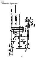
Страница 48: ...VC V50S VC V80T VC V91T 50 POWER CIRCUIT BLOCK DIAGRAM ...

Страница 49: ... resistance ohm is omitted k 1000 ohm M 1 Meg ohm 2 All resistors are 1 8 watt unless otherwise noted 3 Theunitofcapacitance F isomitted µ µF p µµF 4 The values in parentheses are the ones in the PB mode the values without parentheses are the ones in the REC mode VOLTAGE MEASUREMENT CONDITIONS 1 DC voltages are measured between points indi cated and chassis ground by VTVM with AC110 240V 50 60Hz s...

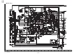
Страница 50: ...C V80T VC V91T 52 53 1 2 3 4 5 6 7 8 9 10 11 12 13 14 15 16 17 18 19 20 A B C D E F G H I J VOLTAGE MEASUREMENT MODE PB Parentheses REC Without Parentheses 9 SCHEMATIC DIAGRAM AND PWB FOIL PATTERN MAIN CIRCUIT 1 ...

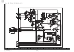
Страница 51: ...VC V50S VC V80T VC V91T 54 55 VOLTAGE MEASUREMENT MODE PB Parentheses REC Without Parentheses MAIN CIRCUIT 2 1 2 3 4 5 6 7 8 9 10 11 12 13 14 15 16 17 18 19 20 A B C D E F G H I J ...

Страница 52: ...C V50S VC V80T VC V91T 56 57 1 2 3 4 5 6 7 8 9 10 11 12 13 14 15 16 17 18 19 20 A B C D E F G H I J VOLTAGE MEASUREMENT MODE PB Parentheses REC Without Parentheses MAIN CIRCUIT 3 AND LED CIRCUIT VC V91T ...

Страница 53: ...VC V50S VC V80T VC V91T 58 59 1 2 3 4 5 6 7 8 9 10 11 12 13 14 15 16 17 18 19 20 A B C D E F G H I J VOLTAGE MEASUREMENT MODE PB Parentheses REC Without Parentheses MAIN CIRCUIT 4 ...

Страница 54: ...VC V50S VC V80T VC V91T 1 2 3 4 5 6 7 8 9 10 11 12 13 14 15 16 17 18 19 20 A B C D E F G H I J VOLTAGE MEASUREMENT MODE PB Parentheses REC Without Parentheses MAIN CIRCUIT 5 60 61 ...

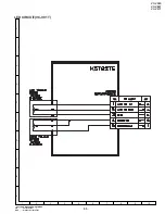
Страница 55: ...VC V50S VC V80T VC V91T 62 VOLTAGE MEASUREMENT MODE PB Parentheses REC Without Parentheses A B C D E F G H I J 1 2 3 4 5 6 7 8 9 10 OPEREATION CIRCUIT ...

Страница 56: ...VC V50S VC V80T VC V91T 63 VOLTAGE MEASUREMENT MODE PB Parentheses REC Without Parentheses A B C D E F G H I J 1 2 3 4 5 6 7 8 9 10 LED CIRCUIT VC V91T ...

Страница 57: ...VC V50S VC V80T VC V91T 64 65 1 2 3 4 5 6 7 8 9 10 11 12 13 14 15 16 17 18 19 20 A B C D E F G H I J PWB FOIL PATTERN MAIN PWB ...

Страница 58: ...VC V50S VC V80T VC V91T 66 A B C D E F G H I J 1 2 3 4 5 6 7 8 9 10 LED PWB VC V91T OPERATION PWB ...

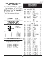
Страница 59: ...T IC6102 VHiBA15218F2E V BA15218F Mic Amp AE V91T IC6103 VHiBA15218F2E V BA15218F Mix Amp AE V91T IC6104 VHiBA15218F2E V BA15218F Mix Amp AE V91T TRANSISTORS Q251 VS2SA1037KQ 1 V 2SA1037KQ AA Q301 VS2SD1306 E1E V 2SD1306 V80T V91T AD Q302 VS2SD1306 E1E V 2SD1306 V80T V91T AD Q303 VSKRC103S 1 V KRC103S AA Q306 VS2SA1037KQ 1 V 2SA1037KQ AA Q501 VSKRC103S 1 V KRC103S AA Q502 VSKRC103S 1 V KRC103S AA ...

Страница 60: ...c AB C505 VCKYCY1HF223Z V 0 022 50V Ceramic AB C506 VCEA9M1HW105M V 1 50V Electrolytic AB C507 VCKYCY1CF104Z V 0 1 16V Ceramic AA C508 VCEA9M1HW475M V 4 7 50V Electrolytic AB C509 VCKYD41CY103N V 0 01 16V Ceramic AA C510 VCCCCY1HH8R0D V 8p 50V Ceramic AA C512 VCKYCY1HF103Z V 0 01 50V Ceramic AA DIODES AND LED S D801 RH PX0252GEZZ J LED Take Up Reel Sensor AF D802 RH PX0252GEZZ J LED Supply Reel Se...

Страница 61: ...102GEZZ J 680p 400V Ceramic AE å C911 VCFYZP2GA473K V 0 047 400V AC å C912 RC KZ0129GEZZ J 150p 1kV Ceramic AC å C913 VCKYPA1HB472K V 4700p 50V Ceramic AA å C914 VCQYTA1HM473J V 0 047 50V Mylar AA å C915 VCQYTA1HM473J V 0 047 50V Mylar AA å C916 VCQYTA1HM562J V 0 0056 50V Mylar AA å C917 VCQYTA1HM333J V 0 033 50V Mylar AA C513 VCKYCY1HF103Z V 0 01 50V Ceramic AA C514 VCKYCY1HF103Z V 0 01 50V Ceram...

Страница 62: ...VRD RA2BE332J V 3 3k 1 8W Carbon AA R314 VRS CY1JF152J V 1 5k 1 16W Metal Oxide AA V80T V91T R315 VRS CY1JF152J V 1 5k 1 16W Metal Oxide AA V80T V91T R330 VRS CY1JF222J V 2 2k 1 16W Metal Oxide AA R331 VRS CY1JF102J V 1k 1 16W Metal Oxide AA R351 VRS CY1JF473J V 47k 1 16W Metal Oxide AA V80T V91T R352 VRS CY1JF473J V 47k 1 16W Metal Oxide AA V80T V91T C921 RC QZ0107GEZZ J 560p 100V Mylar AC C922 V...

Страница 63: ...R866 VRS CY1JF103J V 10k 1 16W Metal Oxide AA R870 VRS CY1JF561J V 560 1 16W Metal Oxide AA R871 VRS CY1JF331J V 330 1 16W Metal Oxide AA R872 VRS CY1JF331J V 330 1 16W Metal Oxide AA R873 VRS CY1JF153J V 15k 1 16W Metal Oxide AA R876 VRS CY1JF102J V 1k 1 16W Metal Oxide AA R877 VRD RA2BE102J V 1k 1 8W Carbon AA R879 VRD RA2BE103J V 10k 1 8W Carbon AA R881 VRD RA2EE121J V 120 1 4W Carbon AA R353 V...

Страница 64: ... R6114 VRS CY1JF153J V 15k 1 16W Metal Oxide AA V91T R6115 VRS CY1JF103J V 10k 1 16W Metal Oxide AA V91T R6116 VRS CY1JF153J V 15k 1 16W Metal Oxide AA V91T R6117 VRS CY1JF563J V 56k 1 16W Metal Oxide AA V91T R6118 VRS CY1JF000J V 0 1 16W Metal Oxide AA V91T R6119 VRS CY1JF563J V 56k 1 16W Metal Oxide AA V91T R6121 VRS CY1JF273J V 27k 1 16W Metal Oxide AA V91T R6122 VRS CY1JF823J V 82k 1 16W Metal...

Страница 65: ...S CY1JF684J V 680k 1 16W Metal Oxide AA V91T R6182 VRS CY1JF563J V 56k 1 16W Metal Oxide AA V91T R6184 VRS CY1JF153J V 15k 1 16W Metal Oxide AA V91T R6185 VRS CY1JF681J V 680 1 16W Metal Oxide AA V91T R6186 VRS CY1JF152J V 1 5k 1 16W Metal Oxide AA V91T R6189 VRS CY1JF153J V 15k 1 16W Metal Oxide AA V91T R6190 VRS CY1JF563J V 56k 1 16W Metal Oxide AA V91T R6319 VRS CY1JF123J V 12k 1 16W Metal Oxid...

Страница 66: ...TEX4 V Upper and lower drum BU Ass y V80T V91T 65 QBRSK0041GEZZ J Drum Earth Brush AD 66 XBPSD26P05J00 V Drum Drive Motor AA Mounting Screw SW2 6P 5S 67 PGiDC0056GEFW J Drum Base AL 68 QPWBF5468AJZZ V PWB LDG Motor AE 69 QPLGZ0292GEZZ J Socket LDG Motor AE 70 MSPRC0223AJFJ V Azimuth Spring AC 71 MSPRC0224AJFJ V Height Adjusting spring AC SCREW NUTS AND WASHERS 201 XBPSD26P08000 V Screw 2 6P 8S A C...

Страница 67: ... AK 514 HDECQ2114AJSB V Cassette Flap V50S AM 514 HDECQ2112AJSA V Cassette Flap V80T AK 514 HDECQ2111AJSA V Cassette Flap V91T AK 515 JBTN 2999AJSA V FF REW Button V50S AE 515 JBTN 2999AJSB V FF REW Button AE V80T V91T 516 PSPAZ0544AJZZ V Volume Knob Spacer AD Karaoke Model Only V91T 517 JKNBP1092AJSB V Slide Knob AE 518 PGiDM0184AJSB V Slide Guide AD 519 HDECP0244AJSA V Foot Decoration AC V80T V9...

Страница 68: ... OF MECHANICAL PARTS MECHANISM CHASSIS PARTS 31 12 20 18 214 19 29 49 51 8 11 203 49 51 7 58 52 4 25 24 2 33 15 1 50 218 207 67 207 53 216 41 61 21 38 17 208 60 47 44 6 30 36 9 39 45 219 10 30 40 27 43 46 43 35 35 37 34 23 48 209 210 211 212 213 223 5 68 69 55 16 202 222 221 201 202 202 220 59 70 57 71 56 32 22 63 62 66 66 66 66 65 62 ...

Страница 69: ...No Description Code Ref No Part No Description Code VC V50S VC V80T VC V91T 77 CASSETTE HOUSING CONTROL PARTS A B C D E F G H 1 2 3 4 5 6 301 304 311 311 305 306 309 303 312 316 315 307 314 310 317 313 302 308 300 ...

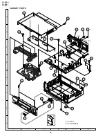
Страница 70: ... No Part No Description Code VC V50S VC V80T VC V91T 78 CABINET PARTS A B C D E F G H 1 2 3 4 5 6 V80T V91T V50S 605 600 608 608 610 602 606 605 614 607 604 617 618 608 619 608 620 601 613 603 616 615 609 611 2 1 1 VC V91T 2 VC V50S V80T ...

Страница 71: ...g Keep the cassette over about 45 open and make sure that the cassette cover open le ver is between the front panel and the cassette cover Now fix the front panel in place Before attaching the front panel in position make surethatthecassettecover open lever is in its right place lower most If it is outofposition pushitdown with a finger A B C D E F 1 2 3 4 5 6 Cassette cover open lever Cassette ho...

Страница 72: ...SPAKP0114AJZZ Polystyrene Sack SPAKC4384AJZZ V50S SPAKC4385AJZZ V80T SPAKC4387AJZZ V91T Packing Case SSAKA0001AJZZ Polyethylene Bag Accessories TiNS 3819AJZZ Operation Manual V50S TiNS 3820AJZZ Operation Manual V80T TiNS 3821AJZZ Operation Manual V91T RMiCD0014GEZZ Microphone V91T QCNW 8379AJZZ 75 ohm Coaxial Cable Battery RRMCG1216AJSA V50S RRMCG1218AJSA V80T V91T Infrared Remote Control Unit 12 ...

Страница 73: ...Ref No Part No Description Code Ref No Part No Description Code VC V50S VC V80T VC V91T 81 ...

Страница 74: ...aita Tochigi 329 2193 Japan COPYRIGHT C 2001 BY SHARP CORPORATION ALL RIGHTS RESERVED No part of this publication may be reproduced stored in a retrieval system or transmitted in any form or by any means electronic mechanical photocopying recording or otherwise without prior written permission of the publisher D SEM P SMM TQ1007 S Jan 2001 Printed in JAPAN SA DS ...

Отзывы: