27
VC-V50S
VC-V80T
VC-V91T
5. ELECTRICAL ADJUSTMENT
Notes:
• Before the adjustment:
Electrical adjustments discussed here are often required after replacement of electronic components and mechanical
parts such as video heads.
Check that the mechanism and all electric components are in good working condition prior to the adjustments,
otherwise adjustments can not be completed.
• Instruments required:
Colour TV monitor
Dual-trace oscilloscope
Audio signal generator
AC milli-voltmeter
Blank video cassette tape
Alignment tape (VROCPSV)
Screwdriver for adjustment
Colour bar signal generator
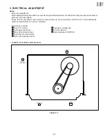
• Location of controls and test points
Figure 5-1.
P201
(TP202-3)
T601
R875
TP701-2
Содержание VC-V50S
Страница 46: ...VC V50S VC V80T VC V91T 8 BLOCK DIAGRAM SYSTEM SERVO BLOCK DIAGRAM 46 47 ...
Страница 48: ...VC V50S VC V80T VC V91T 50 POWER CIRCUIT BLOCK DIAGRAM ...
Страница 58: ...VC V50S VC V80T VC V91T 66 A B C D E F G H I J 1 2 3 4 5 6 7 8 9 10 LED PWB VC V91T OPERATION PWB ...
Страница 73: ...Ref No Part No Description Code Ref No Part No Description Code VC V50S VC V80T VC V91T 81 ...

