VC-V50S
VC-V80T
VC-V91T
38
NO
NO
NO
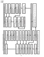
FLOW CHART NO.9 CASSETTE CONTROL TROUBLESHOOTING(2)
A cassette tape is taken in, but ejected at once.
Does the start sensor pulse at
pin(4) of IC801 change from "L" to
"H" level when the cassette tape is
loaded?
Check line between start sensor
and all the way up to IC801.
Does the end sensor pulse at pin(5)
of IC801 change from "L" to "H" level
when the cassette tape is loaded?
Check line between end sensor
and all the way up to IC801.
Does the master cam mode shifter
operate normally when the cassette
tape is loaded?
Check line between cam switch
and all the way up to IC801.
Replace IC801.
YES
YES
YES
FLOW CHART NO.10 LOADING MOTOR AND EJECT TROUBLESHOOTING
The cassette tape fails to come out.
Does the capstan motor start when
the STOP/EJECT button is pressed?
See
FLOW CHART NO.11
CAPSTAN MOTOR TROUBLE
SHOOTING.
Does the take-up reel disk turn when
the capstan motor is running?
Check reel disk and reel drive unit.
Are pulses applied at pin(30) of IC801
when the take-up reel disk is turning?
Check between take-up reel sensor
and all the way up to IC801.
Is a "H" (about 0.7V) level applied
at pin(6) of IC802 when a reel pules
has been inputted?
Check pin(60) of IC801.
Is the voltage about 10V sent out from
pin(10) of IC802?
Check IC802.
Is the specified voltage applied at
the loading motor terminal?
Check between IC802 and all the
way up to the loading motor.
Dose the loading motor run?
Replace loading motor.
Replace cassette cam, gear, etc.
YES
YES
YES
YES
YES
YES
YES
NO
NO
NO
NO
NO
NO
NO
Содержание VC-V50S
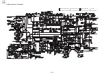
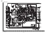
Страница 46: ...VC V50S VC V80T VC V91T 8 BLOCK DIAGRAM SYSTEM SERVO BLOCK DIAGRAM 46 47 ...
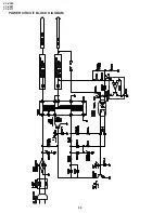
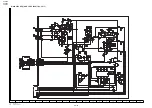
Страница 48: ...VC V50S VC V80T VC V91T 50 POWER CIRCUIT BLOCK DIAGRAM ...
Страница 58: ...VC V50S VC V80T VC V91T 66 A B C D E F G H I J 1 2 3 4 5 6 7 8 9 10 LED PWB VC V91T OPERATION PWB ...
Страница 73: ...Ref No Part No Description Code Ref No Part No Description Code VC V50S VC V80T VC V91T 81 ...


