VC-V50S
VC-V80T
VC-V91T
44
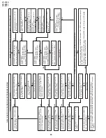
Playback picture does not appear.
YES
YES
YES
YES
YES
YES
YES
YES
YES
NO
NO
YES
YES
YES
YES
YES
YES
YES
NO
NO
NO
NO
NO
NO
NO
NO
NO
NO
NO
NO
Is V-H.SW.P. applied to the
pin(81) of IC201?
Although picture playback is possible, color does not appear in PAL or NTSC mode.
Is voltage 5V applied to the CCD section power terminal at pin(36) of IC201?
Is CCD control voltage (approx. 0V<PAL/MESECAM mode>, 5.0V<NTSC mode>) applied normally to
the pin(37) from the (57) of IC201?
Is clock signal (approx. 8.86MHz<PAL mode>, 7.16MHz<NTSC mode> /0.5 Vp-p) for CCD applied
normally to the pin(44) from the (69) of IC201?
Check between the pins(24) and (23) of
IC201. (Check C210.)
Replace IC201.
Is picture signal output to the emitter of
video output buffer(Q251)?
Is luminance signal (approx. 0.5Vp-p)
input to the pin(26) of IC201?
Is luminance signal (approx. 0.3Vp-p)
input to the pin(42) of IC201?
Is luminance signal (approx. 0.5Vp-p)
input to the pin(19) of IC201?
Is FM signal (approx. 0.4Vp-p) input to
the pin(78) of IC201?
Is FM signal (approx. 0.4Vp-p) output to
the pin(79) of IC201?
Is luminance signal (approx. 0.5Vp-p)
output to the pin(39) of IC201?
Check between the pin(39) and pin(26)
of IC201. (Check C212.)
Check between the pins(21) and (42)
of IC201. (Check C208.)
Check between the pins(18) and (19)
of IC201. (Check C206.)
Check between the pins(55) and (54) of
IC201. (Check R504, L502, C515~6.)
Check between the pins(79) and (78)
of IC201. (Check C312.)
Is luminance signal (approx. 0.25Vp-p)
input and output to the pins(13), (14) and
(17) of IC201, respectively?
Is voltage 5V applied to the chroma
power terminal at pin(61) of IC201?
Is chroma signal
(approx.
156mVp-p<PAL mode>,
298mVp-p<NTSC mode>/
burst) input into the pin(46) of IC201?
Is chroma signal
(approx.
197mVp-p<PAL mode>,
375mVp-p<NTSC mode>/
burst) input into the pin(58) of IC201?
Is chroma signal
(approx.
300mVp-p<PAL mode>,
286mVp-p<NTSC mode>/
burst) input the pin(54) of IC201?
Is chroma signal
(approx.
197mVp-p<PAL mode>,
375mVp-p<NTSC mode>/
burst) output in the pin(35) of IC201?
Check between the pin(60) and (46) of
IC201. (Check C512.)
Check between pin(58) and (35) of IC201.
(Check RJ18, C515.)
Check peripheral of pin(61) of IC201
and PC 5V line.
Check the peripheral circuit of pins(13),
(14) and (16) of IC201. (Check R201-3,
L201, C203, C205.)
<For NTSC mode.>
Check whether the pins(73) and (71) of
IC201 oscillate 3.58MHz?
<For PAL/MESECAM mode.>
Check whether the pins(73) and (75) of
IC201 oscillate 4.43MHz?
Check V-H.SW.P. line.
Replace IC201.
1
Line output : Check video output buffer(Q251) perpheral and output terminal perphery.
2
RF output : Check video output buffer(Q251) perpheral and video input terminal of RF converter
perphery.
FLOW CHART NO.19 PLAYBACK MODE TROUBLESHOOTING
YES
Is luminance signal (approx. 0.5Vp-p)
input to the pin(23) of IC201?
YES
Is picture signal outputted to the pin(52)
of IC201?
YES
YES
<For NTSC mode.>
Check peripheral parts of X501.
<For PAL/MESECAM mode.>
Check peripheral parts of X502.
Содержание VC-V50S
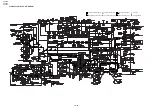
Страница 46: ...VC V50S VC V80T VC V91T 8 BLOCK DIAGRAM SYSTEM SERVO BLOCK DIAGRAM 46 47 ...
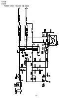
Страница 48: ...VC V50S VC V80T VC V91T 50 POWER CIRCUIT BLOCK DIAGRAM ...
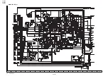
Страница 58: ...VC V50S VC V80T VC V91T 66 A B C D E F G H I J 1 2 3 4 5 6 7 8 9 10 LED PWB VC V91T OPERATION PWB ...
Страница 73: ...Ref No Part No Description Code Ref No Part No Description Code VC V50S VC V80T VC V91T 81 ...


