


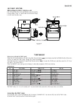


SD-CX1W
– 12 –
Figure 12-1
15
MD Mechanism
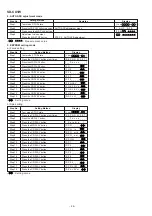
1. Screw ................. (Q1) x4
12-1
holder (Left/Right)
16
Shield Cover
1. Screw ................. (R1) x5
12-1
(Top/Side/Bottom)
2. Screw ................. (R2) x1
17
MD Mechanism
1. Flat Cable ........... (S1) x3
12-1
2. Socket ................ (S2) x2
3. Flexible PWB ..... (S3) x1
18
MD Main PWB
1. Screw ................. (T1) x2
12-1
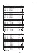
STEP
REMOVAL
PROCEDURE
FIGURE
SD-CX1W (MD MECHANISM UNIT)
Figure 12-3
1
Rear Cabinet
1. Screw ................. (A1) x6
12-2
2
Tweeter
1. Screw ................. (B1) x4
12-3
3
Woofer
1. Screw ................. (C1) x4
12-3
STEP
REMOVAL
PROCEDURE
FIGURE
CP-CX1W
Figure 12-2
(A1)x6
ø4x16mm
Net
Front Panel
Rear Cabinet
(S1)x2
(R2)x1
ø
2x2mm
(R1)x1
ø
2x3mm
(R1)x1
ø
2x3mm
(R1)x1
ø
2x3mm
(R1)x1
ø
2x3mm
(S1)x1
(S2)x1
(S2)x1
(R1)x1
ø
2x3mm
(T1)x2
ø
1.7x3mm
(S3)x1
(Q1)x2
ø
3x6mm
(Q1)x2
ø
3x6mm
Shield Cover,Top
MD Mechanism
Shield Cover,Side
Shield Cover,Bottom
MD Main PWB
Optical pickup
Flexible PWB (Note 1)
(Note 1)
After removing the flexible PWB for optical pickup from the connector
wrap the front end of flexible PWB in conductive aluminum foil so as
to protect the optical pickup from being damaged electrostatically.
Pull
Pull
MD Mechanism
Holder (Right)
MD Mechanism
Holder (Left)
(B1)x4
ø4x12mm
(C1)x4
ø4x12mm
Net
Front Panel
Woofer
Tweeter
Содержание SD-CX1W(BL)
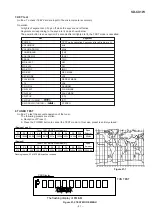
Страница 56: ...SD CX1W 56 Figure 56 WIRING SIDE OF P W BOARD 3 13 A B C D E F G H 1 2 3 4 5 6 TUNER PWB A2 TOP VIEW ...
Страница 114: ...SD CX1W 15 M E M O ...
Страница 115: ...SD CX1W 16 M E M O ...


