


SD-CX1W
– 30 –
Rotating the loading motor forcibly
The loading motor can be rotated forcibly by rotating the VOL
UP/DOWN button while STOP or EJECT in the test mode
appears on the display.
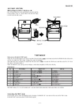
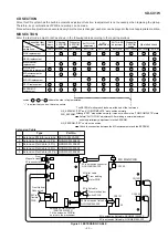
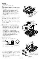
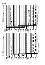
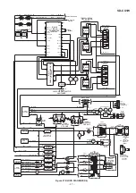
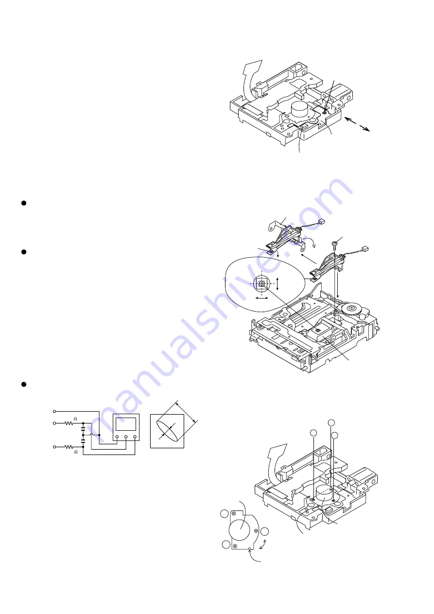
Check of the magnetic head fixing position
• Be sure to check the fixing position of the magnetic head
when replacing the magnetic head and the optical pickup.
• Move the optical pickup to the center in order to make the
fixing position adjustment easy.
1. Secure the magnetic head to the optical pickup with
screw (B1) x 1 pc.
2. Set the transparent disc for checking the head.
3. Lower the magnetic head up shift arm manually to lower
the magnetic head.
4. Check whether the magnetic head aligns with the optical
pickup objective, seeing the set from above.
5. Check that the magnetic head goes up and down
smoothly. (See Fig. 30-2.)
Figure 30-2
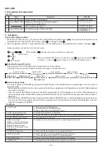
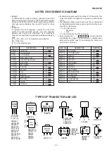
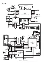
Figure 30-3 Optical Pickup Grating Deviation Measuring
Method
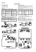
Mechanism Adjustment
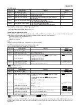
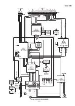
1. Optical pickup grating inspecting method
After auto adjustment (COMPLETE appears) in the test mode
(auto) using the high reflection MD disc TGYS1, adjust the
Lissajou's waveform (x-y) of EOUT to FOUT.
1. Slightly loosen the 3 screws of the spindle motor, adjust
while observing the Lissajou's waveform.
2. After adjustment, tighten screws 1, 2, and 3 in numerical
order. (See Fig. 30-4.)
Figure 30-4
GND CH1
CH2
X
Y
100K
470p
470p
a
b
100K
Osilloscope
Lissajous's waveform
4 Pin of IC1201
GND (TP1202)
11 Pin of IC1201
EIN (TP1253)
12 Pin of IC1201
FIN (TP1254)
Less then a:b = 4:1
Figure 30-1
2. Confirmation
Check that the display shows "_COMPLETE_" instead of
"#COMPLETE_" in step 4 of the AUTO adjustment mode.
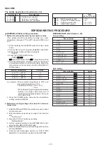
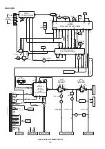
1. Adjustment
Load a high-reflective TGYS1 test disc.
Note:
Adjust the position of the lead-in switch between FF85 to
FFD2.
1. Loosen the screw (A1) x 1 pc., fixing the mechanism
switch PWB.
2. Retighten the screw while pushing the PWB in the
direction of arrow A if the switch position is at FF85 or
lower, or in the direction of arrow B if it is at FFD2 or
higher, and measure its position again.
3. After adjusting the position, fix it with the screw (A1) x 1
pc. (See Fig. 30-1.)
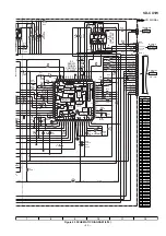
(A1)x1
A
B
MD Mechanism
Switch PWB
Lead In Switch
It is lowered
by hand.
(B1)x1
ø1.7x5mm
Magnetic head up shift arm
Down
Magnetic
head
Objective
lens
Radiai
Tangential
direction
Optical Pickup
2
3
1
2
3
1
Adjusting
hole
Check the Lissajou's waveform,
shifting the mounting position with
a screwdriver (to be fitted into the
spindle motor adjusting hole).
Spindle Motor
Spindle Motor
Содержание SD-CX1W(BL)
Страница 56: ...SD CX1W 56 Figure 56 WIRING SIDE OF P W BOARD 3 13 A B C D E F G H 1 2 3 4 5 6 TUNER PWB A2 TOP VIEW ...
Страница 114: ...SD CX1W 15 M E M O ...
Страница 115: ...SD CX1W 16 M E M O ...


