MX-M503N MX-FN10 7 – 2
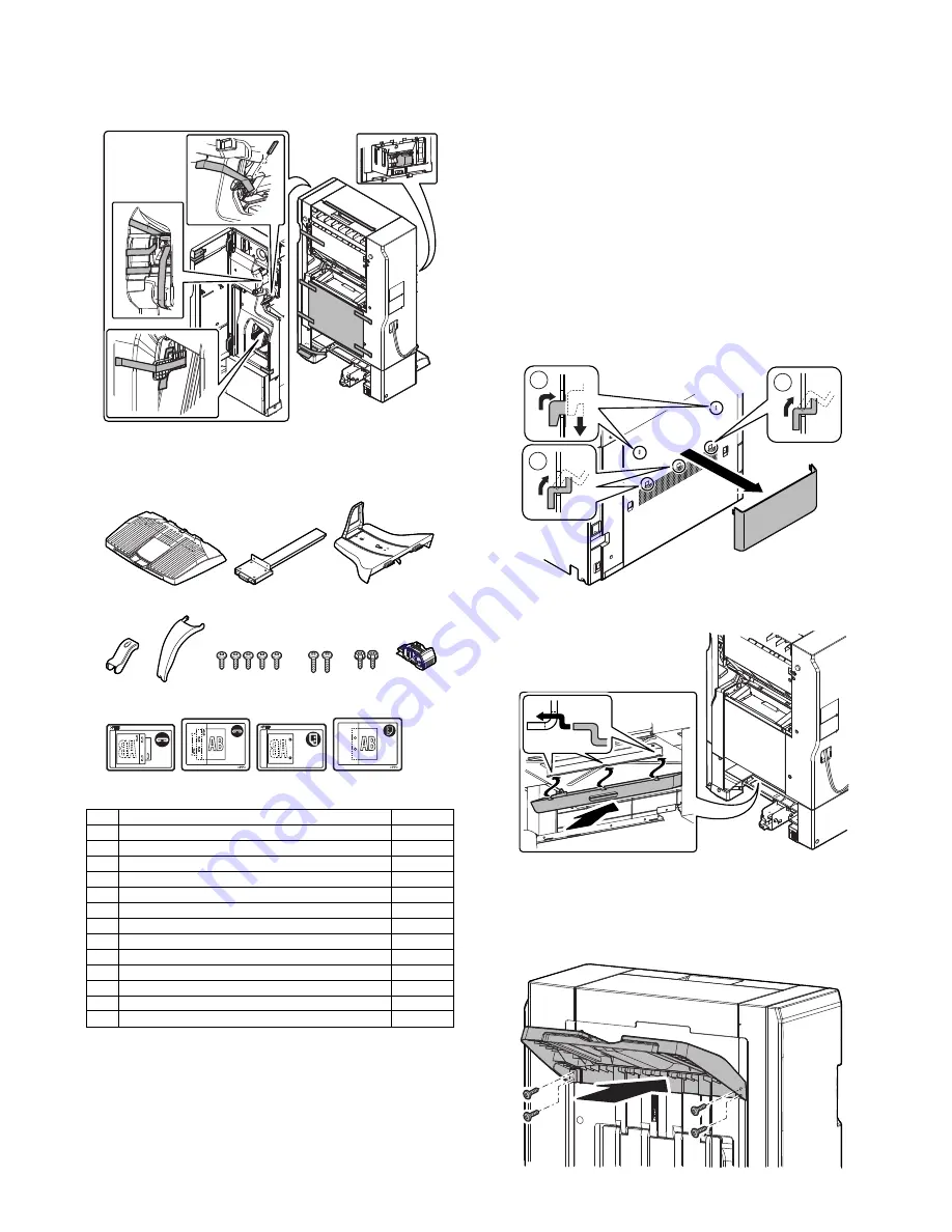
B. Removal of the fixing tape and protection
material
1)
Remove the fixing tape and protection material.
C. Check the packed items
1)
Check that all the items are included in the package.
* The punch position labels (No.12 and No.13) should be kept at
hand since they will be necessary when installing the punch unit.
2. Installation
<Note before installation>
* Make sure that none of the data lamps on the operation panels
are lit or flashing before starting the installation work.
* Installing the MX-FN10 requires that the option desk (MX-DEX8/
DEX9) and junction unit (MX-RBX3) be installed in advance. Be
sure to complete the installation of the option desk (MX-DEX8/
DEX9) and junction unit (MX-RBX3) before installing the saddle
finisher.
* Make sure that the connection plate provided on the front side of
the option desk is securely installed.
Make sure that the connection plate (package part No. 2)
included in the package is securely installed.
A. Replacement of the Operation Manual storage
cover
1)
Remove the Operation Manual storage cover on the left side of
the machine.
2)
Install the Operation Manual storage cover (which was
removed from the machine) to the saddle finisher.
B. Installation of the paper exit tray
1)
Engage the pawls (two positions) of the paper exit tray (pack-
age part No. 1) on the finisher.
Fix the paper exit tray with fixing screws A (package part No.
6).
No.
Packed part names
Quantity
1
Paper exit tray
1
2
Connection plate
1
3
Saddle tray
1
4
Paper holding A
1
5
Paper holding B
1
6
Fixing screw A
5
7
Fixing screw B
2
8
Fixing screw C
2
9
Staple cartridge
1
10
Staple position label (For scanner)
1
11
Staple position label (For RSPF/DSPF)
1
12
Punch position label (For scanner)
1
13
Punch position label (For RSPF/DSPF)
1
1
2
3
5
4
6
7
8
9
10
11
12
13
2
2
1


