9
·
7
9
(1) Instruction system
The PC's application instruction F-202/203 (open channel), F-204 (sending instruction), and F-204
(receive instruction) to send and receive data between modules in a network, and from a module in a
network to an upper stream computer is used.
• In this instruction, the function is completed after the target station replies. A special program is
not needed in the connected PC station. If the target station is an upper computer, a program is
required for response after decoding the SEND/RECEIVE instructions.
But if the upper computer cannot decode the SEND/RECEIVE instructions, these instructions
can not be used.
· SEND/RECEIVE functions of instruction system cannot be communicated two hierarchical layer.
Input conditions of F-202/204/205 instructions should keep being ON until finishing execution of
the instruction (when error flag or carry flag turns to ON.)
• If the input condition is turned OFF during execution of the instruction, the instruction ends in an
incomplete condition. Under this condition, next, when this instruction is given, it will come to a
“communication jam,” and the instruction will not be executed. Turn the power OFF and then ON
again for recovery.
Take any measure for the cases below:
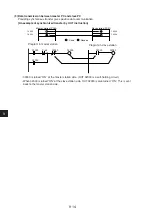
• In case that on instantaneous power failure of min. 10ms occurs and the input conditions turn to
OFF.
[Countermeasure] Change the input conditions to a latched relay.
However if you turn OFF and ON the power during execution of the instruction
while the input condition is set to a latched relay, the JW-20CM will come to
the following state.
F-204/205 instruction processing which is being executed is deleted, and
rising edge of input signal can not be detected for the input condition is kept
ON so that this instruction can not be executed.
[Countermeasure] All flags (07354 to 07357) are turned to OFF. Detect them with the timer, and
operate the next instruction after resetting the input conditions.
Note: The SEND/RECEIVE instruction is not allowed to use 10 to 2C
(H)
as the file numbers for the
communication target station. The data memory start system can use these numbers.
s
t
n
e
t
n
o
c
n
o
i
t
a
c
i
n
u
m
m
o
C
d
e
s
u
e
b
o
t
n
o
i
t
c
u
r
t
s
n
I
)
e
g
a
p
e
e
s
(
)
M
C
0
2
-
W
J
/
W
Z
r
o
f
(
.
n
o
i
t
a
t
o
n
l
a
t
c
o
n
i
n
o
i
t
a
t
s
t
e
g
r
a
t
n
o
i
t
a
c
i
n
u
m
m
o
c
y
f
i
c
e
p
S
)
6
2
-
3
1
(
2
0
2
-
F
)
n
o
i
t
c
u
r
t
s
n
i
D
N
E
S
(
n
o
i
t
a
t
s
d
e
i
f
i
c
e
p
s
e
h
t
n
i
a
t
a
d
e
t
i
r
W
)
7
2
-
3
1
(
4
0
2
-
F
)
n
o
i
t
c
u
r
t
s
n
i
E
V
I
E
C
E
R
(
n
o
i
t
a
t
s
d
e
i
f
i
c
e
p
s
e
h
t
f
o
t
u
o
a
t
a
d
d
a
e
R
)
8
2
-
3
1
(
5
0
2
-
F
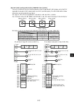
Master station
00
(8)
Slave station
01
(8)
Slave station
02
(8)
Slave station
03
(8)
Writing and
reading data
Response

