5
·
3
5
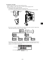
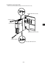
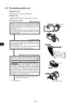
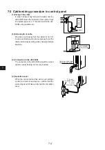
(2) Installation of JW-20CM
Attach the basic rack panel using the two attachment screws.
Before installation or removal, make sure to shut OFF the power supply to the PC.
(Example) Install on basic rack panel JW-4BU
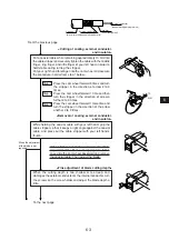
· This module can be installed in any one of the optional slots.
· Be careful not to bend the connector pins on the module by applying too much force to them.
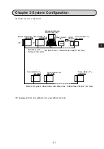
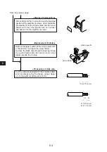
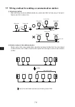
· More than one modules of JW-20CM can be installed on one basic rack panel. However they
cannot communicate by crossing-over another network.
· Optional slots have each port numbers. When an error occurs, the JW-20CM stores the port
number corresponding to the error occurred module into system memory #050 in the PC. This is
applied only error code 53: Optional error.
Module
Basic rack
panel
Phillips
screwdriver
② ③ ④ ⑤ ⑥ ⑦
(Ex.: JW-13BU)
Control module
Port number
▲
Slave
station
B
Master
Station
Slave
station
C
Slave
station
C
Slave
station
C
Slave
station
C
Slave
station
B
Master
Station
Master
station
A
Unavailable
communication between
A and C.
Available communication
between A and B, B and
C, B and B, and C and C.


