XL-30H/30W
– 12 –
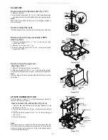
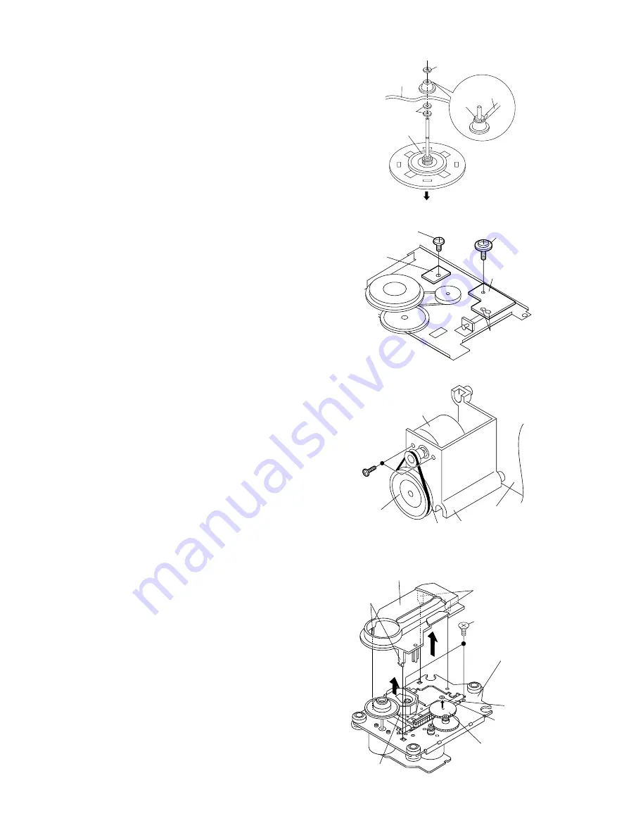
Figure 12-4
How to remove the pickup (See Fig. 12-4)
1. Remove the mechanism cover, paying attention to the
pawls (A1) x 4 pcs.
2. Remove the screws (A2) x 2 pcs., to remove the shaft (A3)
x 1 pc.
3. Remove the stop washer (A4) x 1 pc., to remove the gear
(A5) x 1 pc.
4. Remove the pickup.
CD MECHANISM SECTION
Perform steps 1, 2 and 10, 11 of the disassembly method to
remove the CD mechanism.
Pickup Unit
(A2) x2
ø2.6 x6mm
(A1) x2
CD Mechanism
Shaft
(A3) x1
Gear
(A5) x1
StopWasher
(A4) x1
Mechanism Cover
(A1) x2
How to remove the tape mechanism PWB
(See Fig. 12-2.)
1. Remove the screws (F1) x 1 pc., to remove the tape
mechanism PWB.
2. Remove the screws (F2) x 1 pc.
3. Remove the solder joints (F3) x 2 pcs., to remove the tape
mechanism PWB.
How to remove the jog motor
(See Figs. 12-3.)
1. Remove the side panel and top cabinet.
2. Remove the jog belt (G1) x 1 pc., from the motor pulley.
3. Remove the screws (G2) x 2 pcs., to remove the jog motor.
Note:
When putting on the belt, ascertain that the belt is not twisted,
and clean it.
Figure 12-2
Figure 12-3
(G2)x2
ø2x5mm
Worm
Gear
Jog Belt
(G1)x1
Jog Motor
Holder
Jog Motor
Display PWB
Figure 12-1
How to remove the flywheel (See Fig. 12-1.)
1. Remove the belt.
2. Remove the stop washer (E1) x 1 pc., with a small precision
screwdriver to extract the flywheel from the capstan metal.
Note:
When the stop washer is deformed or damaged, replace it
with a new one.
How to reinstall the parts
Install each part in the reverse order of the removal with care.
Stop
Washer
Driver
(E1)x1
Stop Washer
Mechanism
Chassis
Washerx2
Flywheel
Tape
Mechanism
PWB
Tape
Mechanism
PWB
(F3)x2
Solder
Joint
(F2)x1
ø2x8mm
(F1)x1
ø2x3mm
Note:
After removing the connector for the optical pickup from the
connector, wrap the conductive aluminium foil around the
front end of connector remove to protect the optical pickup
from electrostatic damage.
All manuals and user guides at all-guides.com


