– 49 –
XL-30H/30W
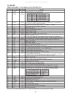
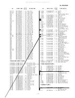
39
AVDD
—
Analog system power terminal.
40
RFCT
Input
RFRP signal center level input terminal.
41
RFZI
Input
RFRP zero cross input terminal.
42
RFIP
Input
RF ripple signal input terminal.
43
FEI
Input
Focus error signal input terminal.
44
SBAD
Input
Sub-beam addition signal input terminal.
45
TSIN
Input
Test input terminal. To be fixed to Vref usually.
46
TEI
Input
Tacking error input terminal. (Tracking servo ON: Taking-in).
47
TEZI
Input
Tracking error, zero cross input terminal.
48
FOO
Output
Focus equalizer output terminal.
49
TRO
Output
Tracking equalizer output terminal.
50
VREF
—
Analog standard power terminal.
51
RFGC
Output
RF amplitude adjustment control signal output terminal.
3-value PWM signal is output. (PWM carrier = 88.2 kHz)
52
TEBC
Output
Tracking balance control signal output terminal.
3-value PWM signal is output. (PWM carrier = 88.2 kHz)
53
FMO
Output
Feed equalizer output terminal. 3-value PWM signal is output. (PWM carrier = 88.2 kHz)
54*
FVO
Output
Speed error signal or feed search EQ output terminal.
3-value PWM signal is output. (PWM carrier = 88.2 kHz)
55
DMO
Output
Disc equalizer output terminal.
3-value PWM signal is output. (PWM carrier = DSP system 88.2 kHz, sync with PXO)
56
2VREF
—
Analog standard power terminal (2xVREF)
57
SEL
Output
APC circuit ON/OFF signal output terminal.
When laser is ON and UHS = L, "Hi-Z". When UHS = H, "H" output is obtained.
58*
FLGA
Output
Internal signal monitor external flag output terminal.
TEZC, FOON, FOK and RFZC signals can be selected with command.
59*
FLGB
Output
Internal signal monitor external flag output terminal.
DFCT, FOON, FMON and RFZC signals can be selected with command.
60*
FLGC
Output
Internal signal monitor external flag output terminal.
TRON, TRSR, FOK, and SRCH signals can be selected with command.
61*
FLGD
Output
Internal signal monitor external flag output terminal.
TRON, DMON, HYS and SHC signals can be selected with command.
62
VDD
—
D power terminal.
63
VSS
—
Digital ground terminal.
64*
IO0
Input/Output
General-use I/O port.
65*
IO1
The input port and output port can be selected with command. In case of input port the terminal
66*
IO2
state (H/L) can be read with the read command.
67*
IO3
In case of output port the terminal state (H/L/HiZ) can be controlled with command.
68*
/DMOUT
Input
Terminal to set the mode to output 2-value PWM of feed equalizer from IO0,1 terminal and 2-
value PWM of disc equalizer from IO2,3 terminal. "L" active
69*
/CKSE
Input
To be opened usually.
70*
/DACT
Input
DAC test mode terminal. To be opened usually.
71
TESIN
Input
Test input terminal (externally provided VCO clock input terminal). To be fixed to "L" usually.
72
TESIO1
Input
Test input/output terminal. To be fixed to "L" usually.
73
VSS
—
Digital ground terminal.
74
PXI
Input
DSP system clock oscillation circuit input terminal. To be fixed to "L" usually.
75*
PXO
Output
DSP system clock oscillation circuit output terminal.
76
VDD
—
D power terminal.
77
XVSS
—
System clock oscillation circuit ground terminal.
78
XI
Input
System clock oscillation input terminal.
79
XO
Output
System clock oscillation circuit output terminal.
80
XVDD
—
System clock oscillation c power terminal.
81
DVSR
—
R channel D/A converting section power terminal.
82
RO
Output
R channel data forward rotation output terminal.
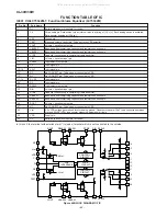
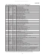
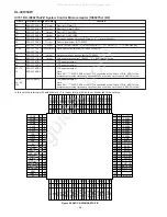
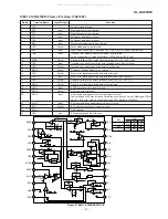
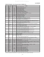
IC802 VHiTC9462F/-1: Servo/Signal Control (TC9462F) (2/3)
Pin No.
Port Name
Function
Input/Output
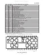
In this unit, the terminal with asterisk mark (*) is (open) terminal which is not connected to the outside.
All manuals and user guides at all-guides.com

