– 11 –
XL-30H/30W
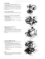
TAPE MECHANISM SECTION
Perform steps 1 to 7 and 9 of the disassembly method to
remove the tape mechanism. (See page 10.)
How to remove the record / playback and erase
heads (See Fig. 11-2.)
1. Remove the screws (A1) x 2 pcs., to remove the erase
head.
2. Remove the screws (A2) x 2 pcs., to remove the record/
playback head.
Note:
After replacing the heads and performing the azimuth
adjustment, be sure to apply screwlock.
How to remove the pinch roller (See Fig. 11-3.)
1. Carefully bend the pinch roller pawl in the direction of the
arrow
<A>
, and remove the pinch roller (B1) x 1 pc.,
upwards.
How to remove the belts (See Fig. 11-4.)
1. Remove the main belt (C1) x 1 pc., from the motor pulley.
2. Remove the FF/REW belt (C2) x 1 pc., from the REW/FF
roller.
3. Put on the belts in the reverse order of removal.
Note:
When putting on the belt, ascertain that the belt is not twisted,
and clean it.
How to remove the motor
(See Figs. 11-5.)
1. Remove the main belt.
2. Remove the screws (D1) x 2 pcs., to remove the motor
bracket.
3. Remove the screws (D2) x 3 pcs., to remove the motor.
Note:
When mounting the motor, pay attention to the motor mounting
angle.
Figure 11-2
Figure 11-3
Figure 11-4
Figure 11-5
<A>
Pinch Roller
(B1)x1
Pinch Roller
Pawl
REMOVING AND REINSTALLING THE MAIN PARTS
Main Belt
(C1)x1
FF/REW Belt
(C2)x1
REW/FF
Clutch
Motor
1
Speaker
1. Front panel .......... (A1) x1
11-1
2. Screw .................. (A2) x4
STEP
REMOVAL
PROCEDURE
FIGURE
CP-XL40H
Figure 11-1
(A2)x4
ø4x12mm
(A1x1)
Woofer
Speaker Box
Driver
Direction of handle
Driver should be
pried away from
speaker Box.
Erase Head
Record/
Playback Head
(A1)x2
ø2x8mm
(A2)x1
ø2x3mm
(A2)x1
ø2x7mm
(D1)x1
ø2x4mm
(D2)x3
Special
Screw
Motor
Bracket
Motor
Motor
(D1)x1
ø2x4mm
Note:
After removing the connector for the optical pickup from the
connector, wrap the conductive aluminium foil around the
front end of connector remove to protect the optical pickup
from electrostatic damage.
All manuals and user guides at all-guides.com
all-guides.com


