


ENGLISH
EN-4
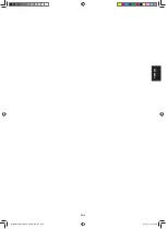
L1 L2 2
A
L1 L2
2
B
L1 L2 2
C
L1L2
L1 L2
2
D
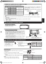
0.2 inch
(5 mm)
A
B
C
D
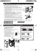
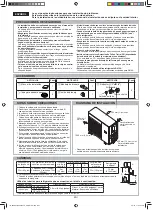
Power supply cable
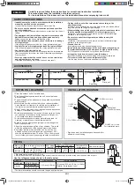
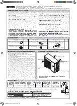
• Fit a disconnect switch, having a contact separation of at least
0.12 inch (3 mm) in all poles, to the electricity power line.
Prepare a dedicated power supply circuit.
For the connections, see below.
Supply power
208/230 V, single-phase
Guaranteed voltage
187-253 V
Max. Fuse
35 A
Min. Circuit Ampacity
23 A
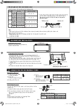
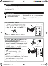
5 POWER CABLING
Cable holder
(8) Remove the cable holder and
connect the cables.
(9) Fix the cable sheath with the
cable holder and the screw.
(10) Double-check that the cable is
securely in place.
(11) Attach the side cover and the
cable cover.
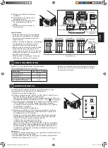
Connecting cable
L1 L2 2
L1 L2 2
L1 L2 2
L1 L2 2
L1 L2 2
L1 L2 2
L1 L2 2
L1 L2 2
L1 L2
A
B
C
D
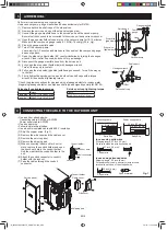
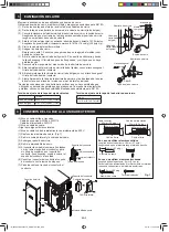
Outdoor unit
Indoor unit A
Power supply
208/230V 60Hz
Ground
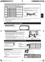
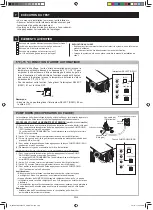
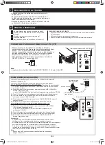
Miswiring of connecting cable will be self-corrected by the wire check operation.
(1) Turn the circuit breaker on.
(2) Check that all LED(LED1A, LED1B, LED1C, LED1D) on the display board
are fl ashing simultaneously.
If one or more of the LED is/are kept lit, check for mismatching terminal
markings(L1, L2, 2,
) and correct them.
(3) To start the wire check, press the WIRE CHECK button(SW2) for 5
seconds or more.
The operation lamp on the indoor unit will fl ash, and three BEEP will
be emitted.
All LED will fl ash rapidly.
(4) When wire check is completed normally, all LED will fl ash
simultaneously and the operation will stop. (Wire check time: 10 - 20
minutes)
When self-correction can not done, all LED will indicate triple fl ash for
eight times and the operation will stop. Check and correct following
points.
• Check all pipings are connected.
• Check the stop valves are open.
After correction, repeat the wire check again. If error is still detected,
or other types of LED signal should be indicated, please contact
a service technician. (Refer to wiring diagram attached inside the
outdoor unit for self diagnosis signal.)
Note:
• For two and three indoor units, the LED for the indoor unit which is not
connected will keep lighting.
• Wire check may not be performed when the outdoor temperature is below
41 °F (5°C).
SW1
DSW1
SW2
PUMP DOWN
SELECT
WIRE CHECK
LED1A
LED1B
LED1C
LED1D
OFF
1
2
ON
WIRE CHECK button (SW2)
6 WIRE CHECK
Indoor unit B
Indoor unit C
Indoor unit D
Disconnect switch
Caution:
• Be very careful not to confuse the terminal
connections. Wrong cabling may damage
the internal control circuit.
• Be sure to connect the cable to match the
markings on the outdoor unit’s terminal
board and those of the indoor unit.
• Be sure to put the cable leads deep into the
terminal board and tighten up the screws.
Poor contact can cause overheating or fi re,
or malfunction.
• Be sure to use a disconnect switch. Follow
the local and state electrical codes.
Earth wire
Earth wire
IM_A3AEX4M3PU(B434)_EN+FR+ES.indb EN-4
IM_A3AEX4M3PU(B434)_EN+FR+ES.indb EN-4
2/7/13 11:05:30 AM
2/7/13 11:05:30 AM


