background image

EN-3

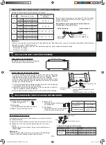
• Use a solid or stranded wire.
  Connecting cable: AWG16 or AWG14
  Power supply cable: AWG12
• Use a copper wire.
• Follow local electrical codes.
• Use a double insulated cable with 600 V insulation. 

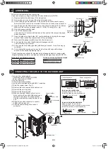
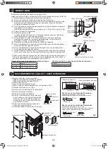
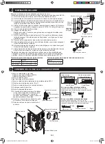
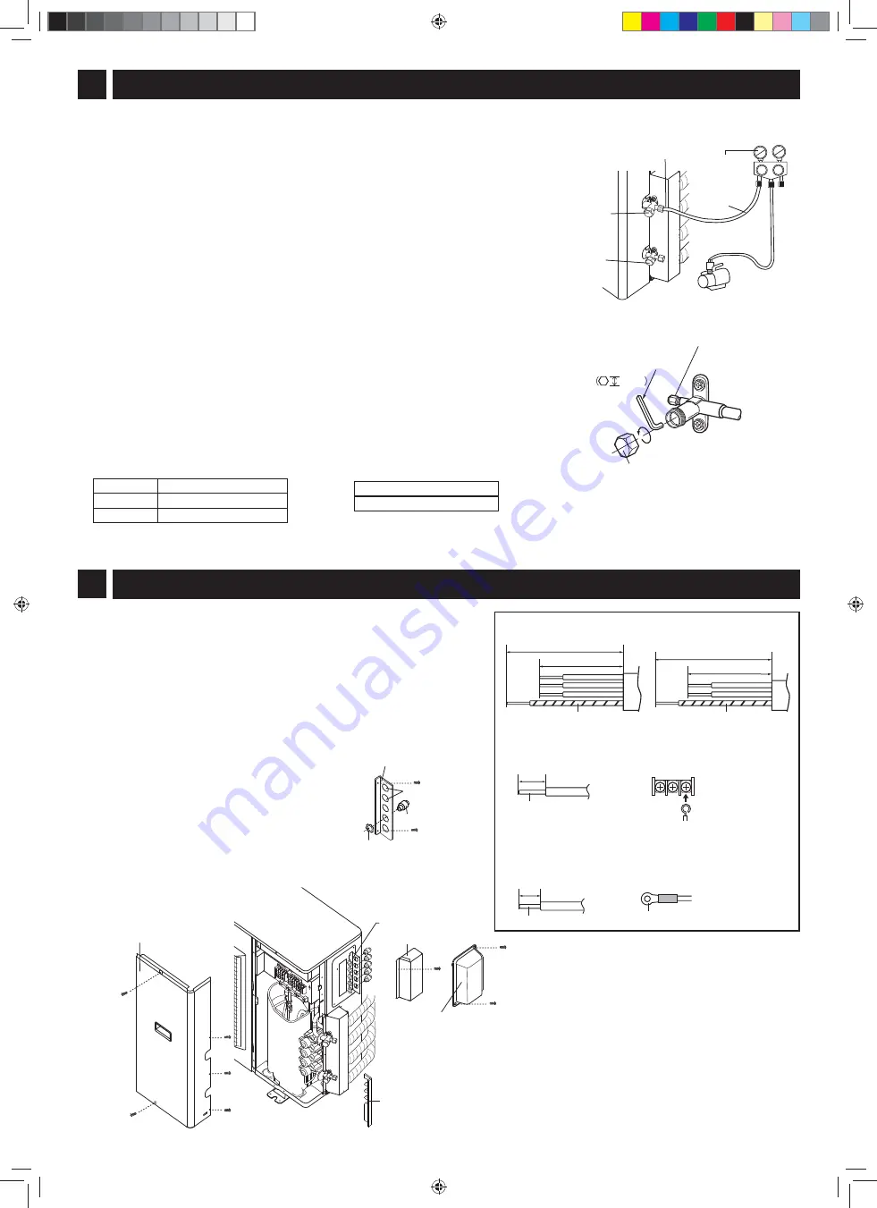
(1) Strip the copper wires. (Fig.1)
(2) Remove the side cover and the cable cover.
(3) Remove the service panel.
(4) Remove the shipping pad.
(5) When connecting indoor unit for 3 unit or 

more, remove the conduit holder and open 
the knock out hole in the conduit holder. 
And then reattach the conduit holder to the 
unit.

(6) Attach the conduit connector to conduit 

holder with the lock nut.

(7) Pass the cables through the conduit 

connector. 

Lo

Hi

Hexagon wrench

Gauge manifold

Compound 
gauge

Perform air removal using a vacuum pump.
Use a vacuum pump, gauge manifold and hoses exclusively for R410A.
(1)  Remove both valve shaft caps of the stop valves.
(2)  Remove the service port cap of the stop valve (gas side).
(3)  Connect the gauge manifold hose to the service port and the vacuum pump.
 

Be sure that the hose end to be connected to the service port has a valve core pusher.

(4)  Open the gauge manifold valve and turn on the vacuum pump for 10-15 minutes.
 

Make sure the compound gauge reads -0.1 MPa(-76 cmHg)(-30 in. Hg). 

(5)  Close the gauge manifold valve.
(6)  Turn off the vacuum pump.
 

Leave as it for 1-2 minutes and make sure the needle of the compound gauge 
does not go back.

(7)  Open the stop valve (liquid side) 90° counterclockwise by turning the hexagon 

wrench. Close it after 5 second, and check for gas leakage.*

(8)  Disconnect the gauge manifold hose from the service port.
(9)  Fully open the stop valve (liquid side) with hexagon wrench. 
 

Turn all the way up to contact.

(10)  Fully open the stop valve (gas side) with hexagon wrench. Turn all the way up 

to contact.

(11)  Firmly tighten the service port cap and both valve shaft caps with a torque 

wrench at the specifi ed tightening torque. 


* Check the pipe connections for gas leak using a leakage detector or soapy water. 

Regarding leakage detector, use high-sensitivity type designed specially for R410A.

Valve shaft cap tightening torque

Torque

Liquid side

17.7±2.1 ft·lbf (24±3 N·m)

Gas side

22.9±2.1 ft·lbf (31±3 N·m)

Valve shaft cap

OPEN

Stop valve 
(gas side)

Stop valve 
(liquid side)

Hose

Service port

Vacuum pump

Service port

4mm

3      AIR REMOVAL

4     CONNECTING THE CABLE TO THE OUTDOOR UNIT

2.2 inch (55 mm)

1.8 inch (45 mm)

1.8 inch (45 mm)

2.6 inch (65 mm)

Connecting cable 

Power supply cable

In case using solid wires

Stripping length: 0.7 inch (18 mm)
Be sure to make the wire hook-shaped.  

Earth wire

Earth wire

Side cover

Service panel

Cable cover

Conduit holder

Shipping pad

0.7 inch (18 mm)

Copper wire

Round terminal 

0.3 inch(8 mm)

Copper wire

In case using stranded wires

Stripping length: 0.3 inch (8 mm)
For power supply cable, securely clamp a round 
terminal to each end of the stripped wire.

Fig.1

Knock out hole

Conduit holder

Conduit connector

Lock nut

Service port cap tightening torque

Torque
8.1±0.74 ft·lbf (11±1 N·m)

IM_A3AEX4M3PU(B434)_EN+FR+ES.indb   EN-3

IM_A3AEX4M3PU(B434)_EN+FR+ES.indb   EN-3

2/7/13   11:05:28 AM

2/7/13   11:05:28 AM

Содержание AE-X4M30PU

Страница 1: ...EUR INDIVIDUEL EN DEUX PARTIES MANUEL D INSTALLATION ACONDICIONADOR DE AIRE TIPO SPLIT MANUAL DE INSTALACIÓN OUTDOOR UNIT AE X4M30PU ENGLISH FRANÇAIS ESPAÑOL IM_A3AEX4M3PU B434 _EN FR ES indb 1 IM_A3AEX4M3PU B434 _EN FR ES indb 1 2 7 13 11 05 27 AM 2 7 13 11 05 27 AM ...

Страница 2: ... installation of outdoor unit only For the installation of the indoor unit see the installation manual accompanying indoor unit SAFETY PRECAUTIONS Tighten the flare nut with a torque wrench according to the specified method If the flare nut is tightened too hard the flare nut may be broken after a long time and cause refrigerant gas leakage When installing the unit take care not to enter air subst...

Страница 3: ...ombination it is possible to install 2 units 15 class 18 class 18 class 18 class Joint 1 2 3 8 Seal ring Flare nut 3 8 Outdoor unit Indoor unit PORT SIZE OF THE OUTDOOR UNIT Base pan cap 2 Connecting the pipes Connect the pipes for the indoor unit first and then for the outdoor unit 1 Tighten the flare nuts by hand for the first 3 4 turns 2 Use a spanner and torque wrench to tighten up the pipes D...

Страница 4: ...wrench Close it after 5 second and check for gas leakage 8 Disconnect the gauge manifold hose from the service port 9 Fully open the stop valve liquid side with hexagon wrench Turn all the way up to contact 10 Fully open the stop valve gas side with hexagon wrench Turn all the way up to contact 11 Firmly tighten the service port cap and both valve shaft caps with a torque wrench at the specified t...

Страница 5: ...leted normally all LED will flash simultaneously and the operation will stop Wire check time 10 20 minutes When self correction can not done all LED will indicate triple flash for eight times and the operation will stop Check and correct following points Check all pipings are connected Check the stop valves are open After correction repeat the wire check again If error is still detected or other t...

Страница 6: ...onnect the gauge manifold hose to the service port of the stop valve gas side 2 To start pump down press the PUMP DOWN button SW1 for 5 seconds or more The OPERATION lamp on the indoor unit will flash and three BEEP will be emitted 3 After 5 10 minutes fully close the stop valve liquid side 4 Close the stop valve gas side when the compound gauge reading becomes almost 0 MPa 0 cmHg 5 To stop the pu...

Страница 7: ...ENGLISH EN 6 IM_A3AEX4M3PU B434 _EN FR ES indb EN 6 IM_A3AEX4M3PU B434 _EN FR ES indb EN 6 2 7 13 11 05 33 AM 2 7 13 11 05 33 AM ...

Страница 8: ...éfrigérant R410A Utilisez les tuyaux de réfrigérant l écrou évasé et les outils exclusive ment pour le R410A REMARQUES SUR LES EMPLACEMENTS 300 mm 1 pi ou plus L installation doit être faite en conformité avec le manuel d ins tallation par un technicien professionnel Un travail incorrect peut provoquer un choc électrique une fuite d eau un incendie Assurez vous d utiliser les accessoires et les pi...

Страница 9: ... intérieures Exceptionnellement dans le cas de la combinaison suivante il est possible d installer 2 unités 15 classe 18 classe 18 classe 18 classe Joint 1 2 po 3 8 po Bague d étanchéité Écrou évasé 3 8 po Unité extérieure Unité intérieure DIMENSION DE L ORIFICE DE L UNITÉ EXTÉRIEURE Bouchon du plateau de base 2 Raccordement des tuyaux Raccordez les tuyaux pour l unité intérieure en premier puis c...

Страница 10: ...es et vérifier s il y a des fuites de gaz 8 Débrancher le tuyau du manomètre de l orifice de l entretien 9 Ouvrir complètement la vanne d arrêt coté liquide avec une clé hexagonale Tournez vers le haut jusqu au contact 10 Ouvrir complètement la vanne d arrêt Côté gaz avec une clé hexagonale Tournez vers le haut jusqu au contact 11 Serrez fermement le bouchon de l orifice d entretien et des deux bo...

Страница 11: ...les DEL clignotent simultanément et l opération s arrête Durée de la vérification de fil 10 20 minutes Lorsque la correction automatique ne peut pas se faire toutes les DEL indiqueront clignoteront 3 fois et ce huit fois puis l opération s arrêtera Vérifier et corriger les points suivants Vérifier si tous les tuyaux sont raccordés Vérifier si les vannes d arrêt sont ouvertes Après correction répét...

Страница 12: ... arrêt côté gaz lorsque la mesure du manovacuomètre devient presque 0 MPa 0 cmHg 5 Pour arrêter la récupération du fluide appuyez sur la touche PUMP DOWN SW1 pendant au moins 5 secondes 6 Débrancher le tuyau du manomètre de l orifice de l entretien PROCÉDURE SANS UTILISER LE MANOMÈTRE DE PRESSION 1 Pour commencer la récupération du fluide appuyez sur la touche PUMP DOWN SW1 pendant au moins 5 seco...

Страница 13: ...FR 6 FRANÇAIS IM_A3AEX4M3PU B434 _EN FR ES indb FR 6 IM_A3AEX4M3PU B434 _EN FR ES indb FR 6 2 7 13 11 05 40 AM 2 7 13 11 05 40 AM ...

Страница 14: ... describe solo la instalación de la unidad exterior Para la instalación de la unidad interior vea el manual de instalación que se adjunta con la unidad interior PRECAUCIONES DE SEGURIDAD Ajuste la tuerca cónica con una llave de torsión según el método indicado Si la tuerca cónica está demasiado ajustada podría rajarse o romperse después de un tiempo y producir pérdida de gas refrigerante Cuando in...

Страница 15: ...ción siguiente es posible instalar 2 unidades Clase 15 clase 18 Clase 18 clase 18 Junta 1 2 3 8 Anillo de sellado Tuerca cónica 3 8 Unidad exterior Unidad interior TAMAÑO DE LA ABERTURA DE LA UNIDAD EXTERIOR Tapa para bandeja base 2 Conectar los caños Conecte los caños de la unidad interior primero y luego los de la unidad exterior 1 Ajuste las tuercas a mano las primeras 3 4 vueltas 2 Utilice una...

Страница 16: ...gas 8 Desconecte la manguera del manómetro de la abertura de servicio 9 Abra completamente la válvula de cierre lado del líquido con una llave hexagonal Gírela del todo hasta el contacto 10 Abra completamente la válvula de cierre lado del gas con una llave hexagonal Gírela del todo hasta el contacto 11 Ajuste firmemente la tapa de la abertura de servicio y las dos tapas de los ejes de válvula con ...

Страница 17: ...simultáneamente y el funcionamiento se detendrá Periodo de verificación del alambre 10 20 minutos Cuando la autocorrección no se pueda realizar todos los LED indicarán un triple parpadeo ocho veces y el funcionamiento se detendrá Compruebe y corrija los siguientes puntos Compruebe que todas las cañerías estén conectadas Compruebe que las válvulas de cierre estén abiertas Después de la corrección r...

Страница 18: ...rvicio de la válvula de cierre lado del gas 2 Para poner en marcha la evacuación presione el botón PUMP DOWN SW1 durante 5 segundos o más La luz de FUNCIONAMIENTO de la unidad interior parpadeará y se emitirán tres PITIDOS 3 Tras 5 10 minutos cierre completamente la válvula de cierre lado del líquido 4 Cierre la válvula de cierre lado del gas cuando la lectura del manómetro compuesto sea casi 0 MP...

Страница 19: ...ES 6 ESPAÑOL IM_A3AEX4M3PU B434 _EN FR ES indb ES 6 IM_A3AEX4M3PU B434 _EN FR ES indb ES 6 2 7 13 11 05 47 AM 2 7 13 11 05 47 AM ...

Страница 20: ...Printed in Thailand TINS B434JBRZ 13A TH 1 IM_A3AEX4M3PU B434 _EN FR ES indb ES 7 IM_A3AEX4M3PU B434 _EN FR ES indb ES 7 2 7 13 11 05 47 AM 2 7 13 11 05 47 AM ...

Отзывы: