


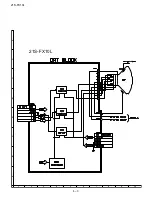


21S-FX10L
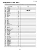
5 – 8
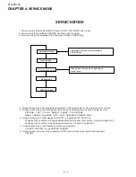
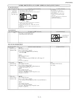
PROTECTOR OPERATION CHECKING
NO
ADJUSTMENT POINT
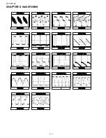
WAVEFORM OR OTHERS
1
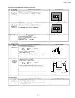
H, V PROTECTOR
(1) Receive US 4 CH LION HEAD Signal (NTSC 60 Hz).
(2) Connect output of Bias Box to
D602
cathode (C602 positive).
(3) Set voltage of Bias Box to
18V
and make sure the protector is not working.
(4) Set voltage of Bias Box to
28.5V
. Make sure the protector is functioned, horizontal oscilation stop
and picture disappear.
(5) Pull out the AC cord at least 4 second before plugging in again (to make sure
-COM has
been reset) for the set to recover from protector mode
2
OTHER PROTECTOR
(1) Once finish rectified Electrolytic Capacitor short testing in + B line,
check all possible damaged components on +B line.
(Use random selected set for inspection)
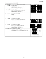
A/V INPUT & OUTPUT CHECKING
NO
ADJUSTMENT POINT
WAVEFORM OR OTHERS
1
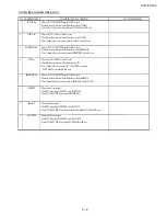
VIDEO AND AUDIO
(1) Receive the "US 10 CH HALF Color Bar" signal.
OUTPUT CHECK
(2) Terminate the Video output with a 75 ohm impedance.
NOTE:
When FAO is set to ON, SPEAKER will
( At signal is standard Color Bar Y/C=1/1, 87.5% Mod.)
automatically turn OFF. TV volume control
Make sure the output is as specified
(1.0 Vp-p ± 3 dB).
is disabled
(3) Terminate the Audio output with a 47K ohm impedance.
( 400 Hz 100 % Mod. 47 k , VOL Max. )
(a) Go to feature menu, set the FAO to OFF
Make sure the O/P is as specified
(2.5 Vp-p ± 0.5Vp-p)
.
(b) Go to feature menu, set the FAO to ON
Make sure the O/P is as specified
(1.2 Vp-p ± 0.3Vp-p)
.
2
VIDEO AND AUDIO
(1) Using the INPUT key on the remote controller, make sure that the modes change in order of
INPUT CHECK
TV, COMPONENT, INPUT1,INPUT2 & TV again and the video & audio output are according
to the input terminal for each mode.
(2) Video cross-talk INPUT to TV checking :
a) When connect INPUT1 input, check TV also
b) When connect INPUT2 input, check TV also
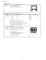
3
COMPONENT IN
(1) Connect YUV & Audio signal to Component In terminal and Audio terminal.
CHECK
(2) Using the INPUT key on the remote controller, press it until the modes change to COMPONENT,
confirm output is appear.
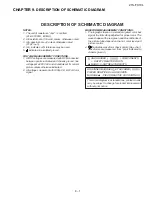
ADJUSTMENT CONDITION / PROCEDURE
ADJUSTMENT CONDITION / PROCEDURE
Содержание 21SFX10L
Страница 27: ...21S FX10L 8 2 19 18 17 16 15 14 13 12 11 10 ...
Страница 28: ...21S FX10L 8 3 A C B D E F G H 2 10 9 8 7 6 5 4 3 1 21S FX10L ...
Страница 31: ...21S FX10L 10 2 19 18 17 16 15 14 13 12 11 10 ...
Страница 32: ...21S FX10L 10 3 A C B D E F G H 2 10 9 8 7 6 5 4 3 1 ...
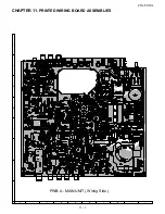
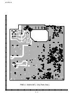
Страница 34: ...21S FX10L 11 2 PWB A MAIN UNIT Chip Parts Side A C B D E F G H 2 10 9 8 7 6 5 4 3 1 ...
Страница 35: ...21S FX10L 11 3 PWB B CRT UNIT Wring Side A C B D E F G H 2 10 9 8 7 6 5 4 3 1 ...
Страница 36: ...21S FX10L 11 4 PWB B CRT UNIT Chip Parts Side A C B D E F G H 2 10 9 8 7 6 5 4 3 1 ...