


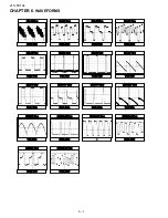


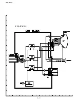
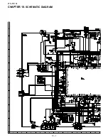


21S-FX10L
5 – 7
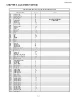
SCREEN, WHITE BALANCE, SUB-BRIGHTNESS & SUB-CONTRAST ADJUSTMENT(2)
NO
ADJUSTMENT POINT
ADJUSTMENT CONDITION / PROCEDURE
WAVEFORM OR OTHERS
3
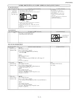
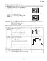
SUB-BRIGHTNESS
(1) In CH 23 50IRE window pattern signal condition.
(to be done after screen,
(2) Using Minolta Color Analyzer CA-100, let the gun point at
Dark White
position
white balance adj)
(as attach drawing), adjust
V04
Bus data until
BRIGHTNESS Y
=
1.5cd/m2
(I2C BUS CONTROL)
4
SUB-CONTRAST
(1) In CH 23 50IRE window pattern signal condition.
(to be done after screen,
(2) Using Minolta Color Analyzer CA-100, let the gun point at
White
position
white balance adj,
(as attach drawing), adjust
V01
Bus data until
BRIGHTNESS Y = 150cd/m2
sub-brightness adj)
(I2C BUS CONTROL)
** NOTE: Allowable Data for V01 >=90, even Y can't match the spec
White
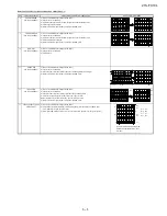
5
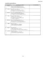
BEAM CURRENT CHECK (1) Receive US 4 CH LION HEAD Signal (NTSC 60 Hz).
(2) Press R/C to set Picture NORMAL condition.
(3) Connect the DC miliammeter between TP 603 ( + ) & TP 602 ( - )
(Full Scale: 3mA Range).
(4) Beam current must be within :
1000 ± 100μA
US14
Dark White
US14
NTSC CHROMA ADJUSTMENT
NO
ADJUSTMENT POINT
ADJUSTMENT CONDITION / PROCEDURE
WAVEFORM OR REMARKS
1
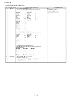
SUB-TINT
(1) Receive the "US 10 CH HALF Color Bar" signal.
(2) Connect the oscilloscope to JA410 or TP853 BLUE-OUT
(I2C BUS CONTROL)
Range
: 500mV/Div (AC)
(Use Probe 10:1)
Sweep time
: 10
μ
sec/Div
(3) Select the service data
V02
. On Y-mute using the R/C.
(4) Adjust the V02 (Sub tint) data to obtain the waveform as shown in Figure 1.1
(B-Amp Base (TP853) must be in stepping level)
*REMARK
: PLEASE MAKE SURE USE RF SIGNAL DURING SUB TINT ADJUSTMENT
Fig 1-1
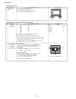
2
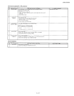
SUB COLOR
(1) Receive the "US 10 CH HALF Color Bar" signal.
(2) Make the image normal with the remote controller.
(I2C BUS CONTROL)
(3) Connect the oscilloscope to JA401 (TP851) RED-OUT.
(to be done after
sub tint adj)
Range
: 500mV/Div (AC)
( Use Probe 10:1)
Sweep time
: 10
μ
sec/Div
(4) Select the service data
V03.
Adjust the
V03
(Sub color) data to obtain the waveform
adjustment shown in Fig. 1-2.
(5) Fig 1.2 waveforms shows that the 75% white & red portions of color bar at the same level
*REMARK
: PLEASE MAKE SURE USE RF SIGNAL DURING SUB COLOUR ADJUSTMENT
Fig 1-2
MS LEVEL ADJUSTMENT
NO
ADJUSTMENT POINT
ADJUSTMENT CONDITION / PROCEDURE
WAVEFORM OR REMARKS
1
MS LEVEL
(1) Receive the "US 10 CH HALF Color Bar" signal.
ADJUSTMENT
(2) Connect the oscilloscope to IC3003 pin 17 ( C3014 -VE).
(I2C BUS CONTROL)
(3) Set the sound volume control more than 1.
(4) Adjust the bus data
M01
until the voltage of IC3003 pin 17 (C3014 -VE) become as follows:
530m (+18m,-35m) Vrms
W
Y
Cy
G
100% WHITE
Mg
R
B
Содержание 21SFX10L
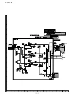
Страница 27: ...21S FX10L 8 2 19 18 17 16 15 14 13 12 11 10 ...
Страница 28: ...21S FX10L 8 3 A C B D E F G H 2 10 9 8 7 6 5 4 3 1 21S FX10L ...
Страница 31: ...21S FX10L 10 2 19 18 17 16 15 14 13 12 11 10 ...
Страница 32: ...21S FX10L 10 3 A C B D E F G H 2 10 9 8 7 6 5 4 3 1 ...
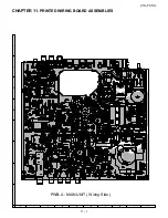
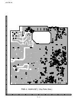
Страница 34: ...21S FX10L 11 2 PWB A MAIN UNIT Chip Parts Side A C B D E F G H 2 10 9 8 7 6 5 4 3 1 ...
Страница 35: ...21S FX10L 11 3 PWB B CRT UNIT Wring Side A C B D E F G H 2 10 9 8 7 6 5 4 3 1 ...
Страница 36: ...21S FX10L 11 4 PWB B CRT UNIT Chip Parts Side A C B D E F G H 2 10 9 8 7 6 5 4 3 1 ...


