


27
13VT-N100
13VT-N150
13VT-CN10
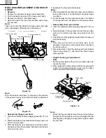
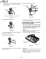
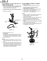
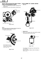
CHECKING THE VIDEO SEARCH REWIND
BACK TENSION
• Remove the cassette housing control assembly.
• After short-circuiting TP7701 and TP7702 pro-
vided at the left on the main PWB, plug in the
power cord, then turn on the power.
• Checking
1. After pressing the play button, press the rewind but-
ton, and set the video search rewind mode.
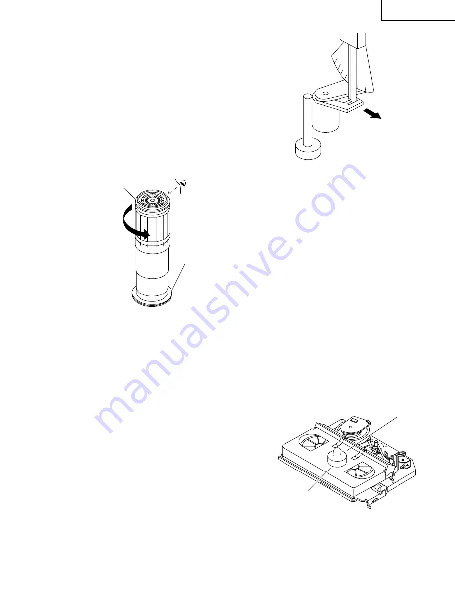
2. Place the torque gauge on the take-up reel disk, and
turn it counterclockwise very slowly (one rotation every
2 to 3 seconds) and check that the torque is within the
set value 3.4 ± 1.5mN
⋅
m (35 ± 15gf
⋅
cm).
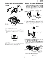
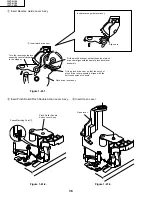
Pinch roller
Tension gauge
900 - 1,200g
Capstan shaft
Tension gauge adapter
Figure 1-12.
Torque gauge
Take-up reel disk
Notes:
Set the torque gauge securely on the take-up reel disk.
If it is not secure, the measurement will be incorrect.
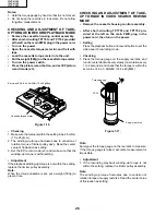
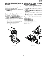
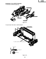
CHECKING THE PINCH ROLLER PRESSURE
• Remove the cassette housing control assembly.
• After short-circuiting TP7701 and TP7702 pro-
vided at the left on the main PWB, plug in the
power cord, then turn on the power.
• Checking
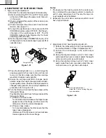
Press the play button to set the playback mode.
CCW
500g
(T-120)
Weight to prevent
float (500g)
Figure 1-13.
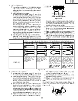
Figure 1-14.
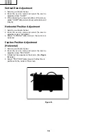
• Checking
1. Set a cassette tape, push the REC button to place the
unit in the SP record mode. Now check the tension
pole position.
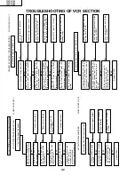
1. Detach the pinch roller from the capstan shaft.
Do not separate excessively. Or the pinch lever and
pinch double action lever may disengage.
2. Engage the tension gauge adapter with the pinch
roller shaft, and pull in the arrow direction.
3. Gradually return the pinch roller, and measure the
pulling force when the pinch roller contacts the cap-
stan shaft.
4. Make sure that the measured value is within setting
0.9 to 11.8 N (900 to 1,200g).
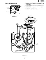
CHECKING AND ADJUSTMENT OF TENSION
POLE POSITION
• Remove the cassette housing control assembly.
• After short-circuiting TP7701 and TP7702 pro-
vided at the left on the main PWB, plug in the
power cord, then turn on the power.
• Setting
1. Open the cassette tape (T-120), and fix with tape.
2. Set the cassette tape in loading state.
3. Put the weight (500g) on the cassette tape.
4. Make the adjustment with the beginning of a T-120
tape.
Содержание 13VT-CN10
Страница 55: ...57 13VT N100 13VT N150 13VT CN10 56 12 11 10 9 8 7 6 5 4 3 2 1 A B C D E F G H BLOCK DIAGRAM OF TV SECTION ...
Страница 61: ...69 13VT N100 13VT N150 13VT CN10 68 12 11 10 9 8 7 6 5 4 3 2 1 A B C D E F G H OVERALL SCHEMATIC DIAGRAM ...
Страница 69: ...83 6 5 4 3 2 1 A B C D E F G H 13VT N100 13VT N150 13VT CN10 PWB C POWER Unit Wiring Side ...
Страница 70: ...84 6 5 4 3 2 1 A B C D E F G H 13VT N100 13VT N150 13VT CN10 PWB A MAIN Unit Wiring Side ...
Страница 71: ...85 6 5 4 3 2 1 A B C D E F G H 13VT N100 13VT N150 13VT CN10 PWB A MAIN Unit Chip Parts Side ...


