


19
13VT-N100
13VT-N150
13VT-CN10
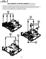
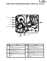
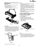
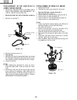
FUNCTION OF MAJOR MECHANICAL PARTS
(BOTTOM VIEW)
No.
Function
No.
Function
6.
Limiter pulley ass’y
Transmits the power of the capstan D.D. motor to
the reel disk via the drive idler.
8.
Shifter
Transmits the operation of the master cam to break
ass’y, Ioading gear, tension arm and clutch lever.
9.
Take-up loading gear
Shifts the take-up pole base and guide roller via the
loading gear T, and applies the tape around the drum
assembly, as well as transmits the power to the
loading gears.
1.
Slow brake
Gets in contact with the capstan D.D. motor
linking to the master cam in the slow still mode,
and brakes it to a certain degree.
3.
Capstan D.D. motor
A motive power which runs the tape. It transmits
the power via the Drive belt.
4.
Drive belt
Transmits the power to run the tape to the Limiter
pulley.
Capstan D. D. Motor
Drive Belt
Slow Brake
Master Cam
Casecon Drive Gear
Clutch Lever
Limiter Pulley Ass'y
Shifter
3
4
1
2
7
5
6
8
Содержание 13VT-CN10
Страница 55: ...57 13VT N100 13VT N150 13VT CN10 56 12 11 10 9 8 7 6 5 4 3 2 1 A B C D E F G H BLOCK DIAGRAM OF TV SECTION ...
Страница 61: ...69 13VT N100 13VT N150 13VT CN10 68 12 11 10 9 8 7 6 5 4 3 2 1 A B C D E F G H OVERALL SCHEMATIC DIAGRAM ...
Страница 69: ...83 6 5 4 3 2 1 A B C D E F G H 13VT N100 13VT N150 13VT CN10 PWB C POWER Unit Wiring Side ...
Страница 70: ...84 6 5 4 3 2 1 A B C D E F G H 13VT N100 13VT N150 13VT CN10 PWB A MAIN Unit Wiring Side ...
Страница 71: ...85 6 5 4 3 2 1 A B C D E F G H 13VT N100 13VT N150 13VT CN10 PWB A MAIN Unit Chip Parts Side ...


