124
System Manual – MOVIDRIVE® compact Drive Inverters
3
Explanation of the parameters
Parameters
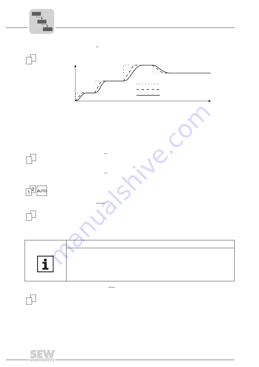
P135 / P145 S pat-
tern t12 / t22
Setting range: 0/1/2/3 (0 = off, 1 = weak, 2 = medium, 3 = strong)
The 2nd ramp (t12/ t22) of parameter sets 1 and 2 can be rounded with 3 pattern grades
to achieve a smoother acceleration of the drive.
A started S pattern is interrupted by the stop ramp t13/t23 and a changeover to ramp
t11/t12. Withdrawing the setpoint or a stop using the input terminals causes the started
S curve to be completed. This allows the drive to continue to accelerate despite the fact
that the setpoint has been withdrawn.
P136 / P146 Stop
ramp t13 / t23
Unit: [s]
Setting range: 0 ... 2 ... 20 s
The stop ramp is activated by withdrawing the ENABLE terminal or by an error (P83x
Fault responses).
P137 / P147 Emer-
gency ramp t14 /
t24
Setting range: 0 ... 2 ... 20 s
The emergency ramp is activated by an error (P83x Fault responses). The system mon-
itors whether the drive reaches zero speed within the set time. After the set time expires,
the output stage is inhibited and the brake applied even if zero speed has not yet been
reached.
P138 Ramp limit
VFC
Setting range: YES / NO
The ramp limitation limits the smallest ramp time in VFC operating modes (P700 Oper-
ating mode 1) to 100 ms (reference:
∆
n = 3000 1/min). Settings less than 100 ms are
ignored and the ramp time 100 ms is applied. The ramp limitation limits the maximum
output current to the value set in P303/P313. Active stall protection is implemented for
the connected motor using the current limiting controller when ramp limitation is activat-
ed.
P139 / P149 Ramp
monitoring 1 / 2
Setting range: YES / NO
If you set the deceleration ramps to a value that is a lot shorter than can be physically
accomplished in this system, the turning drive will be stopped after expiration of the
monitoring time. Such a setting will cause a fault signal and increase brake wear.
1
2
01266BEN
Figure 36: Effect of the S pattern
V
in
t
Setpoint at the input
No S pattern active
With S pattern
1
2
1
2
NOTE
There is no active stall protection for the connected motor when ramp limitation is de-
activated and ramp times of less than 100 ms are used. Parameters P303 Current limit
1 / P313 Current limit 2 will not be effective in this case. If a maximum output current of
185 % of the rated output current is exceeded for more than 60 ms, the inverter switch-
es off with error message F01 Overcurrent and the "Immediate switch-off" error re-
sponse.
1
2
P6..
P60.
P600
Содержание MOVIDRIVE compact MCH41A
Страница 2: ...SEW EURODRIVE Driving the world...
Страница 432: ......


