System Manual – MOVIDRIVE® compact Drive Inverters
137
3
1
2
3
4
5
6
7
8
9
10
11
12
13
14
15
16
17
18
19
20
21
22
Explanation of the parameters
Parameters
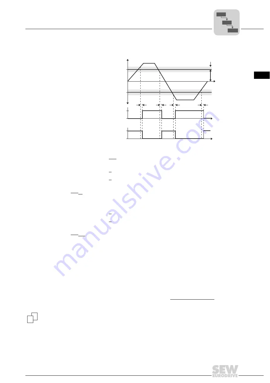
P43x Current
reference signal
Signal if the output current is greater than or less than the reference value.
P430 Current
reference value
Setting range: 0 ... 100 ... 150 % I
N
P431 Hysteresis
Setting range: 0 ... 5 ... 30 % I
N
P432 Deceleration
time
Setting range: 0 ... 1 ... 9 s
P433 Signal = “1“
when:
I < I
ref
/ I > I
ref
P44x Imax signal
Signal if the inverter has reached the current limitation.
P440 Hysteresis
Setting range: 0 ... 5 ... 50 % I
N
P441 Deceleration
time
Setting range: 0 ... 1 ... 9 s
P442 Signal = “1“
when:
I < I
max
/ I = I
max
P5xx Monitoring functions
The following monitoring functions have been implemented to monitor what happens to
drive-specific parameters in the specific application and to be able to react in case of
impermissible deviations. Some of the monitoring functions are available separately in
both parameter sets. The response to the triggering of the monitoring functions can be
set with P83x Fault responses .
P50x Speed monitoring
P500 / P502
Speed monitoring
1 / 2
Setting range: AUS / MOTOR / RGENERATIVE / MOT®EN.MODE
The speed required by the setpoint can only be achieved if there is sufficient torque
available to meet the load requirements. If P303 Current limit 1 / P313 Current limit 2
and the external current limit has been reached, then MOVIDRIVE
®
assumes that the
torque has reached the maximum limit and the desired speed cannot be attained. Speed
monitoring is triggered if this situation persists for the duration specified in P501 Decel-
eration time 1 / P503 Deceleration time 2 .
01623BEN
Figure 43: Current reference signal
I
ref
-I
ref
P431
P430
t
P432
1
1
0
0
t
t
P433: Signal = "1" at | I | > I
ref
P433: Signal = "1" at | I | < I
ref
I [% off I ]
N
1
2
P6..
P60.
P600
Содержание MOVIDRIVE compact MCH41A
Страница 2: ...SEW EURODRIVE Driving the world...
Страница 432: ......


