


Hardware connections
Manual
– ECC-DFC field bus controller
23
4.4.2.
Logic and motor roller current supply
Each module of the fieldbus controller has separate power connections for the
module logic and the motor, so that these can be supplied via separate current
supply units.
For example, the motor current supply can be switched off using an emergency
stop system, so that all motors are de-energized. If the motor current supply op-
erates separately, the logic current supply can remain switched on so that the
module communication is still active and can transmit status messages to moni-
toring systems.
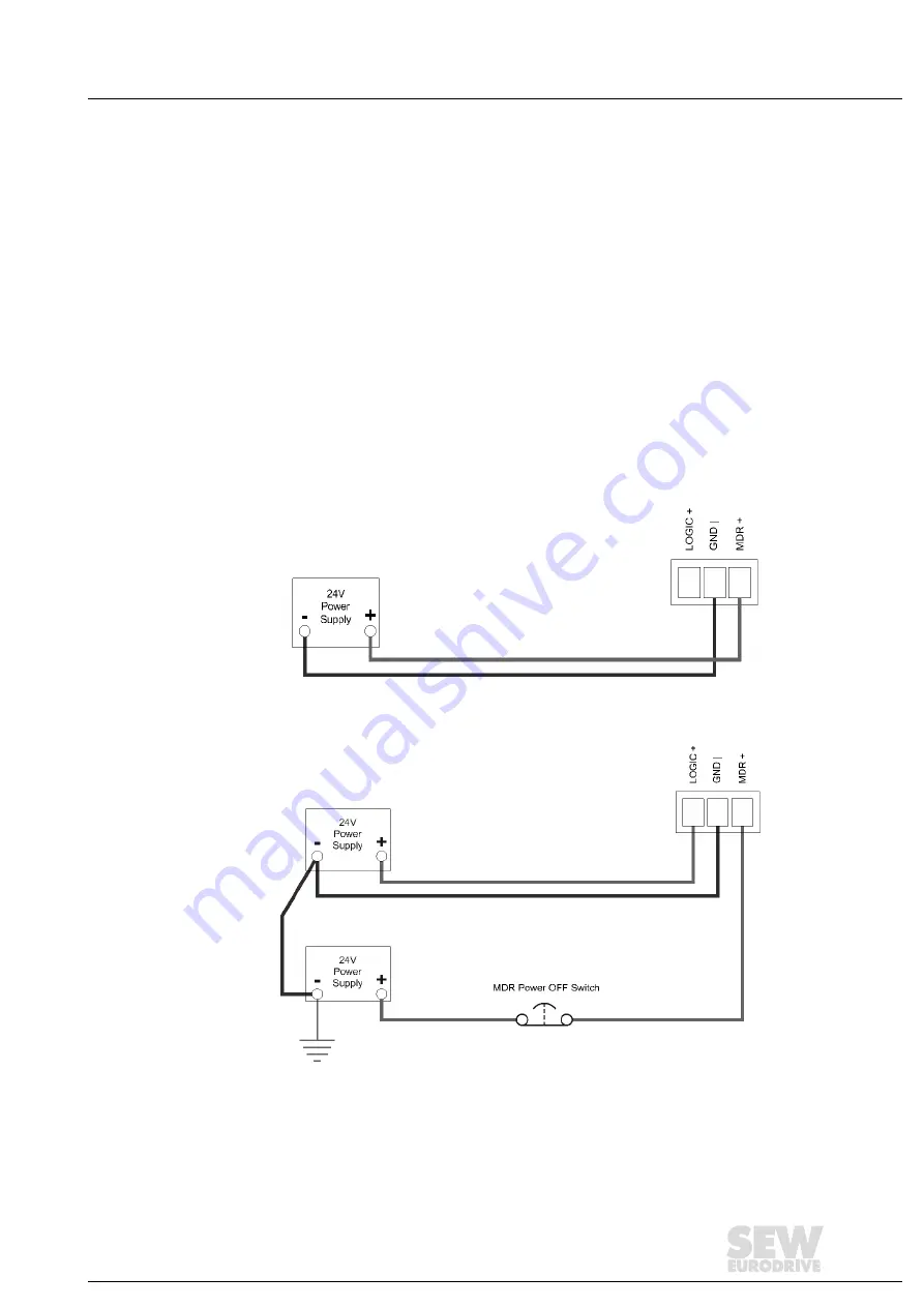
Figure 11 shows a wiring diagram for separate logic and motor roller current
supplies, and the wiring diagram in figure 10 shows the single current supply of
the logic and the motor rollers.
Note that the supply to the motor roller terminal simultaneously also supplies the
logic with power.
Figure 10 Connection of a single current supply for motor rollers and logic
Figure 11 Typical connection of separate current supplies for motor rollers and logic
Содержание ECDriveS ECC-DFC
Страница 2: ...SEW EURODRIVE Driving the world ...
Страница 73: ...ECShell engineering software Manual ECC DFC field bus controller 73 ...
Страница 89: ...Appendix A Dimensions and Installation Instructions Manual ECC DFC field bus controller 89 Dimensions in mm ...
Страница 94: ......
Страница 95: ......