9(21)
Servodan A/S | Tel +45 7442 4726 | Fax + 45 7442 4035 | [email protected] | www.servodan.com
GB
nected load will light at the set minimum.
If the input voltage is 10V, the connected load will light at the set
maximum.
After a power cut, the dimmer switches back to its previous value.
Operation input 2 (terminals 2 -3), see
Fig. 3
:
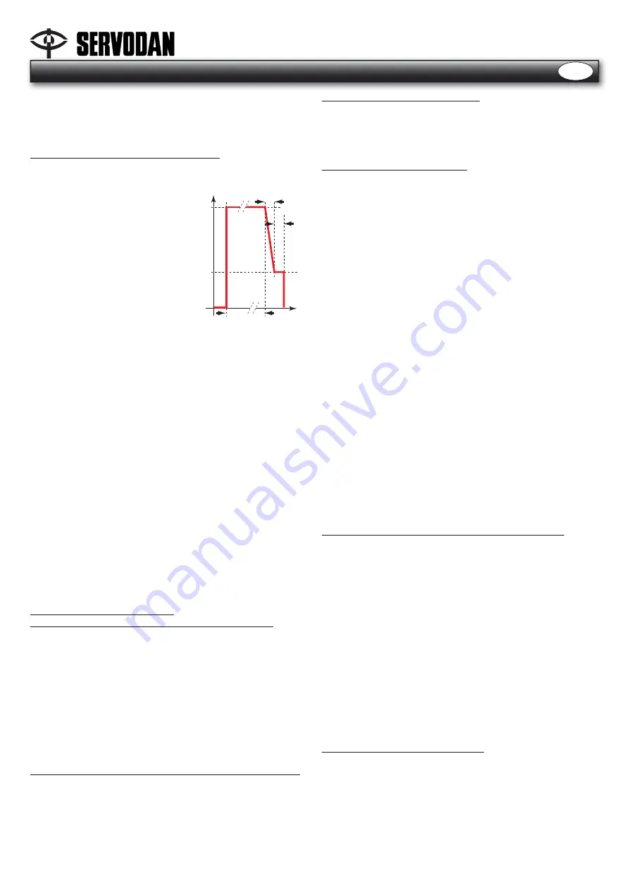
Simple staircase timer
Normal operation:
0%
30%
Max.
tp
15s.
15s.
t
-> light is off
-> press push button briefl y
-> the load is switched on at max.
intensity during an adjustable
time (tp). That time does not start
until you have released the push
button.
-> After this time the load dims to
30% in 15s.
-> After 15s. in this light intensity the
load is switched off.
If the push button is pressed while the load is switched on, dim-
ming down or dimmed to 30%, the load switches back to its
max. intensity and the set time (tp) starts again.
The stairwell timer can be disabled via a lockable push button,
which is placed in parallel with the control.
Modifying the switch-off time (
tp
)
-> Press the push button 5 times in quick succession (intervals of
max. 1s.).
-> The dimmer is in ‘setting time’ mode. This is indicated by the
load continuously dimming up and down.
-> In ‘setting time’ mode, you have 10s. to briefl y press the push
button 1 to 5 times in quick succession.
Pressing the push button once corresponds to a switch-off time
of 1min.
Pressing twice to 3min.
Pressing 3 times to 5min.
Pressing 4 times to 7min.
Pressing 5 times to 9min.
As a standard, the switch-off time is 3min.
-> After 10s., the ‘setting time’ mode will automatically be exited
and changes are being saved.
Mode 2: 1-10V analogue control
Operation input 1 (terminals 3 - 4), adjusting the intensity:
When this mode is selected, the dimmer operates via a voltage
control signal from 1 to 10V according to the EN standard 60929.
From 1 to 10V the light can be adjusted from 1% to maximum
light intensity. The intensity of the current of the control circuit
determines the light level.
If the input voltage is less than the threshold voltage, the con-
nected load will light at the set minimum. If no control signal is
connected, the connected load will light at the set maximum. If
the input voltage is 10V, the connected load will light at the set
maximum. After a power cut, the dimmer switches back to its
previous value.
Operation input 2 (terminals 2 -3), switching the light on and off:
The connected load is switched on when the contact between
input 2 and ‘COM’ is closed. If the connection between input 2
and ‘COM’ is interrupted, the light will be switched off.
See
Fig. 3
Mode 3: single push button control
In the single push button mode, input 1 and input 2 have dif-
ferent and independent functions. Input 1 functions as a single
push button dim function, adjustable with or without memory.
Input 2 allows light scenes to be saved and recalled at any time.
Operation input 1 (terminals 3 - 4):
Input 1 has a single push button dim function (
Fig. 4
).
Memory function:
The dimmer can be used with or without memory. The standard
setting of the dimmer is single push button mode with memory
function. To set the dimmer without memory function, it is suf-
fi cient to press the ‘control’ key for 10s. at max. light level. After
10s., the light will decrease from maximum to 50% to indicate
that the memory function is switched off. Release the push but-
ton immediately after this change in light intensity. If the push
button is not released immediately, there will be no switchover
from ‘with memory’ to ‘without memory’ or vice versa. Repeat
the procedure to reactivate the memory function. This function,
as well as the last set light level, is stored in a non-volatile mem-
ory. The settings will not be lost in the event of a power failure.
With memory function, the dimmer fi rst switches on at the mini-
mum light level. The dimmer then switches on at the last set value.
With memory
Press briefl y = switching on/off, ‘on’ at previous level
Keep pressing = dimming up/down
Keep pressing when dimmer is ‘off” = dimmer dims up from 0%
When dimming up: dimmer stops at maximum value
When dimming down: dimmer stops 2s. at minimum value and
then dims up.
A renewed (long) press reverses the dimming direction.
Without memory
When briefl y switching when ’off’, the dimmer always switches
on at max.level. For the rest, it operates in the same way as ’with
memory’.
Operation input 2 (connection terminals 2 - 3), see
Fig. 4
:
Input 2 allows a light scene to be saved and recalled.
To save a light scene, you proceed as follows:
1. Set the desired light scene by means of input 1.
2. Keep input 2 pressed for 3s. The connected load fi rst dims to
the previous set light scene and after 3s. dims to the desired
light scene.
3. The light scene has been set.
The light scene can be recalled at any time by pressing input 2.
To exit the light scene and switch off the load, use input 1.
It is possible to simultaneously call up the light scenes of differ-
ent light circuits by means of the single push button control. To
this end, connect terminals 2 and 3 of the dimmers that control
the relevant light circuits.
After a power failure the load is switched off.
Multiple switch points with NO contacts can be connected. Up
to 30 NO contacts can be connected in parallel. The maximum
distance is 100m
Mode 4: double push button control
In double push button mode, input 1 (terminals 3 - 4) and input
2 (terminals 2 - 3) together function as a double push button
dimmer (
Fig. 4
).
Memory function:
With memory
Briefl y press input 1: the load is switched on.
Keep input 1 pressed: dimming up.
Keep input 2 pressed: the load is switched on at previous level.


