


FP400 fusion splices
FP400 Product Guide
Page 51
Fusion splicing
The following procedures assume that the sensor cable is correctly deployed with sufficient cable
laid out at the splice location. There are 2 recommended methods for making the field splices.
Depending on the zone configurations at the site, follow either the cut cable applications or the
expressed cable applications.
Recommended tools
The following tools have been tested and are recommended for use with the standard FP400
sensor cable:
•
Miller ACS-2 or equivalent (e.g., CATVSCOPE 4 - 10 mm transverse armored stripping tool)
for outer jacket removal (midspan access ring cut and slitting)
•
Jonard MS-8 midspan slitter
•
RTV sealant
•
isopropyl alcohol and lint free cloth or wipes (e.g., Kim wipes)
•
fiber technicians splicing tools
Cut cable applications
In cut cable applications the sensor cable is cut at the point of the splices and only the fibers
required for the particular configuration are spliced. This method works for single zone
configurations or for two contiguous linear zones.
1.
Determine the location of the splice on the sensor cable and cut the cable at that point.
2.
Pass 50 cm (20 in.) of cable from each cut section through the supplied grommets.
3.
Remove 40 cm (16 in.) of the outer black jacket and FRP strength members to expose the
fiber buffer tube on both cables.
4.
Remove 39.4 cm (15 3/4 in.) of the buffer tube leaving 6 mm (1/4 in.) of tube on each cable.
5.
Trim off the unused fibers (i.e., all fibers except the ones required for the splice).
6.
Thoroughly clean the remaining exposed fibers, the buffer tube and the end of the outer jacket
with alcohol and lint free wipes to remove all of the protective gel and any other contamination.
7.
Make the required fusion splices (2 for processor, 4 for start module, 2 for end module).
8.
Carefully, dress the fibers and fit the module/splice sleeves into the slots in the STP enclosure.
9.
Use RTV sealant to seal the ends of the buffer tubes and to secure the modules and splice
sleeves in the spice tray’s slots.
Expressed cable applications
In expressed cable applications midspan access techniques are used to expose the 12 fibers
around the splice location. Only the fibers required for the particular connection are spliced. The
remaining fibers are left intact and continue beyond the splice. This method works for multi-zone
contiguous configurations.
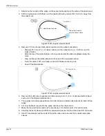
Figure 55 FP400 cut splice connection details
50 cm (20 in.)
40 cm (16 in.)
6 mm (1/4 in.)
Содержание FiberPatrol FP400
Страница 6: ...Page 6 FP400 Product Guide ...
Страница 14: ...FP400 components Page 14 FP400 Product Guide ...
Страница 56: ...FP400 fusion splices Page 56 FP400 Product Guide ...