


Installing the FP400 processor
Page 48
FP400 Product Guide
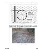
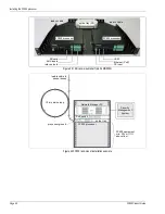
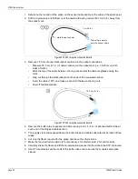
Figure 49 Silver Network fiber optic wiring diagram
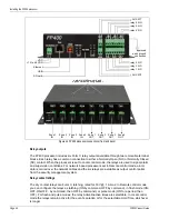
Figure 50 Silver Network Ethernet wiring diagram
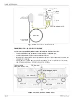
Figure 51: IP-based Silver Network block diagram (with lightning protection)
TXB
RXB
TXA
RXA
TXB
RXB
TXA RXA
TXB
RXB
TXA
RXA
TXB
RXB
TXA
RXA
maximum 60 processors
first processor
second processor
last processor
Network Interface Unit
to Network Manager
maximum distance between processors
multi-mode fiber optic = 2.2 km (1.4 miles)
single-mode fiber optic = 10 km (6.2 miles)
maximum 60 processors
first processor
second processor
last processor
Network
maximum distance
third processor
fourth processor
fifth processor
Manager
computer
security
management
system
computer
between processor
and PoE switch
100 m (328 ft.)
minimum Category 5 Ethernet cable
class 3
PoE
switch
PoE switch
lightning
arrestor
earth
ground
Cat-5e or Cat-6
unshielded Ethernet
100 m (max.)
IP-based
field distribution box
use single point grounding connect one end of the Cat-6 cable shield to ground and leave the other end disconnected
*
*
lightning
arrestor
Cat-5e or Cat-6
unshielded Ethernet
Cat-6 shielded
Ethernet
FP400
equipment room
sensor
Содержание FiberPatrol FP400
Страница 6: ...Page 6 FP400 Product Guide ...
Страница 14: ...FP400 components Page 14 FP400 Product Guide ...
Страница 56: ...FP400 fusion splices Page 56 FP400 Product Guide ...