


Installing the FP400 processor
FP400 Product Guide
Page 45
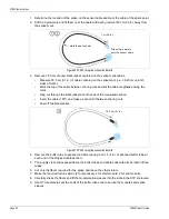
Auxiliary inputs/Self-test inputs
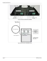
AUX 1 and AUX 2 are voltage sensing inputs. The FP400 processor determines an input’s status
via an internal reference voltage, and the configuration of the contact closures and supervision
resistors.
provides wiring diagrams for self-test and auxiliary device inputs. In Local
control mode the inputs activate internal self-tests. In Remote control mode the AUX inputs serve
as auxiliary device inputs for reporting the status of auxiliary security equipment to the SMS.
Silver Network alarm data communication
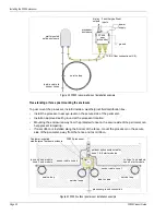
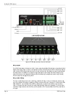
To use a network interface card with the FP400 processor requires an expansion header hardware
kit (p/n F4KT0300). The kit includes an expansion header extender and 2 sets of mounting
hardware (2 each - standoffs, screws, flat washers, lock washers).
CAUTION
The contact closure inputs to AUX 1 and AUX 2 MUST be
voltage-free.
Figure 45 Self-test/Auxiliary device input wiring examples
Note
A network interface card is required to enable EIA-422 copper wire,
Multi-mode fiber optic, and Single-mode fiber optic communications
between a FP400 processor and the Silver Network Manager. Ethernet
communications are built-in via the processor’s PoE port.
AUX 1 AUX 2
-
+
-
+
NO self-test inputs
Local control mode
dual resistor supervision
NO alarm
dual resistor supervision
NC alarm
Remote control mode
cut and short supervision
cut and short supervision
AUX 1 AUX 2
-
+
-
+
NO auxiliary input
unsupervised
NC auxiliary input
unsupervised
Remote control mode
single resistor supervision
NO alarm
single resistor supervision
NC alarm
Remote control mode
cut supervision
short supervision
Содержание FiberPatrol FP400
Страница 6: ...Page 6 FP400 Product Guide ...
Страница 14: ...FP400 components Page 14 FP400 Product Guide ...
Страница 56: ...FP400 fusion splices Page 56 FP400 Product Guide ...