


Buried cable applications
Page 40
FiberPatrol FP1150 Product Guide
•
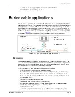
fiber drop point locations (for access to dark fibers in sensor cable)
for a fiber drop point you require an outdoor splice enclosure and splice tray, a buried vault and
a section of conduit with a 90º sweep to bring the fiber optic cable above ground,
Figure 45
illustrates a fiber drop point which includes three 10 m (33 ft.) service loops that are required to
make the fusion splices
Burial media
The soil in which the sensor cable is buried must be a type that conducts vibrations. Most natural
types of soil are included, however, extremely loose soil types like sand and gravel do not conduct
vibrations well and may prevent the sensor from operating efficiently. When conducting the site
survey, make a note of any locations along the cable route that have loose soil types.
Deploying the sensor cable
Typically, FiberPatrol sensor cable is deployed by mounting the cable drum on a reel trailer or a
truck, which lays out the cable on the ground as it moves alongside the pipeline. Refer to the site
plan and pull back and lay out sufficient sensor cable to cover any site specific features (bypasses,
service loops, fiber access points).
The following factors must be considered when deploying FiberPatrol sensor cable:
•
The length of the section of sensor cable being deployed.
•
Clearance and access along the cable route.
•
The location of splices and fiber drop points.
•
Site-specific features such as cable bypasses.
Sensor cable splices
At all designated splice points, each section of sensor cable requires a 10 m (33 ft.) service loop to
provide access to the sensor cable and splice enclosure. Inside the splice tray, the sensor fiber
and any other fibers that are designated for use must be fusion spliced. When dressing the bare
fibers, ensure that the turn radius is kept above a minimum bend radius of 32 mm (1.25 in.). Any
tighter bend radius may lead to optical fiber damage and an increased loss at the splice location.
Once the field splices are complete, and the sensor cable is installed, the loss must be measured
from both ends of the cable to ensure the quality of each splice. The average loss for the full length
of sensor cable must be 0.25 dB per km or less (up to 80 km of sensor cable) or 0.24 dB per km or
less (up to 100 km of sensor cable for pipeline TPI). The fusion splices at the head end and the
end module are made after the field splices have passed the OTDR measurement test. All field
splices are protected inside weatherproof enclosures and buried vaults. There are two splice
enclosures available, one holds a maximum of 24 splices, the other holds up to 48.
Содержание FiberPatrol FP1150 Series
Страница 72: ...Troubleshooting procedures Page 72 FiberPatrol FP1150 Product Guide ...
Страница 124: ...Page 124 FiberPatrol FP1150 Product Guide ...
Страница 134: ...Page 134 FiberPatrol FP1150 Product Guide ...


