


FiberPatrol FP1150 Product Guide
Page 17
2
Site planning
FiberPatrol configurations
The recommended method for installing FiberPatrol sensor cable is to use the minimum number of
splices possible; i.e., run a single length of cable from the equipment room to the fence, and
continue for as far as site conditions will allow you to go. Use splices for the equipment room
connection to the SU, for the end module, and for any fiber drop points.
Loop configurations
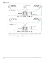
The loop configuration provides single cut cable redundancy for a closed perimeter. The sensor
unit is located anywhere along the perimeter length with the start and end points of the detecting
sensor cables co-located on the protected fence. Non-detecting lead cable carries the signal from
the sensor unit to the start point of the detecting cable. The two sensing fibers S1 and S2 run in
opposite directions around the perimeter. In the event of a cut or severely damaged sensor cable,
detection will continue around the perimeter in both directions to the location of the damage. There
are two types of redundant loop configurations, fully closed and partially closed.
provides a comparison of the two.
Figure 10 FiberPatrol example fully closed & partially closed configurations
FiberPatrol sensor cable
perimeter fence
administration
administration
fully closed perimeter
partially closed perimeter
Содержание FiberPatrol FP1150 Series
Страница 72: ...Troubleshooting procedures Page 72 FiberPatrol FP1150 Product Guide ...
Страница 124: ...Page 124 FiberPatrol FP1150 Product Guide ...
Страница 134: ...Page 134 FiberPatrol FP1150 Product Guide ...


