


1
SELKIRK CORPORATION
5030 Corporate Exchange Blvd. SE,
Grand Rapids, MI 49512
1.800.992.VENT (8368)
&
SUPERVENT (SC & FC)
SUPERPRO (SPR)
©2021 SuperVent / SuperPro
All Rights Reserved
3010122
SELKIRK CANADA CORPORATION
950 South Service Road, Second Floor
Stoney Creek, ON L
8
E 6A5
1.888.SELKIRK(735.5475)
02/
12
/2021
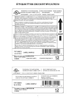
CHEMINÉE ISOLÉE
FABRIQUÉE EN USINE
ET
CAN/ULC-S604
LISEZ TOUTES LES DIRECTIVES AVANT
DE PROCÉDER À L'INSTALLATION. À
DÉFAUT D'INSTALLEZ CE SYSTÈME
SELON CES DIRECTIVES, ANNULERA
LES CONDITIONS DE CERTIFICATION
AINSI QUE LA GARANTIE DU FABRICANT.
CONSERVEZ CES DIRECTIVES DANS UN
ENDROIT SÉCURITAIRE AFIN DE
POUVOIR VOUS REPORTER AU BESOIN
UNE DES CAUSES PRINCIPALES
D’INCENDIES DE CHEMINÉES
EST LE FAIT DE NE PAS
MAINTENIR LE DÉGAGEMENT
REQUIS (ESPACES D’AIR) AUX
MATÉRIAUX COMBUSTIBLES
IL EST DE LA PLUS HAUTE
IMPORTANCE QUE CETTE
CHEMINÉE SOIT INSTALLÉE EN
CONFORMITÉ AVEC CES
DIRECTIVES SEULEMENT
I
NSCRIT
À
LA
NORME
UL 103 T
YPE
HT
Installateur: Il est de la plus haute importance
que ces directives seront laissé avec le
propriétaire.
Propriétaire: Gardez les directives d’installation
et guide d’entretien dans un endroit sécuritaire
pour référence future.
D
IRECTIVES
D
'
INSTALLATION
&
G
UIDE
D
'
ENTRETIEN
(C
ANADA
& É
TATS
-U
NIS
)
LISTÉE


