Selkirk SUPERPRO SPR Скачать руководство пользователя страница 16

16

1.  After framing in your opening to the dimensions specified in Table

1 found in the Framing Details section (measured in the horizontal

plane), slide the Cathedral Support box into the framed opening.

2. Once the box is at the desired height, ensure the box is level and

nail the box to the framing using four 2” spiral nails or #8 x1-1/2"

wood screws per side.  The excess material sticking above the roof can

either  be trimmed off  before attaching the box to the framing or, after

it is installed the corners can be cut and the excess material folded down
onto the roof deck.

The SuperVent/SuperPro Cathedral Ceiling Support will support a

total of 38 feet of chimney of which 15 feet of chimney can be

suspended below the support.  The Cathedral Ceiling Support is

screwed or nailed into framing installed between the roof rafters.

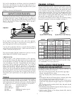
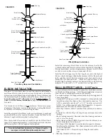
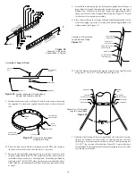
4. Lower the chimney length down through the opening in the bottom
of the support so that the Support Band makes contact with the bottom
of the Support Box.  (See Figure 34).

NOTE:

  The male coupler of each chimney length must be up.  The bottom

chimney length(s) must protrude into the living space so that proper
clearances are maintained from the stove pipe connector to the lower side
of the ceiling.   Refer to Chart 3 on page 22 at the back of these instructions
for proper clearances.  Do not offset the chimney below the Cathedral
Support.  NOTE: A minimum of 1" of the insulated chimney length must
protrude below the Cathedral Support Box for stability.

Cathedral Ceiling Support Installation

FIGURE 34

Storm Collar

Chimney Sections

Rain Cap

Ventilated Flashing

Stove Pipe Adaptor

Support Box

Support  Band

5. Install additional chimney sections and lock together by turning
clockwise until the two sections lock together tightly.  Continue in this
manner until the required height above the roof is achieved.  NOTE:
Unlike normal inside installation, a cathedral installation provides only
one support point for the chimney.  This limited support can allow the
chimney to sway slightly or vibrate in high winds.  It is advisable to install
additional lateral support if the chimney extends more than 3 feet out of
the roof.

NOTE: 

To reduce cold air infiltration into the dwelling you

can install the optional Universal Shielding Insulation (JUSI)

into the Cathedral Support.  See separate installation

instructions  packaged with the JUSI.

3. Install the Support Band on the chimney length at the desired posi-
tion by tightening the draw band bolt and by screwing four stainless
steel sheet metal screws through the draw band and into the outer casing.

Ceiling Trim Angles

Ceiling Trim Angles

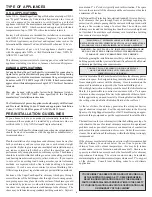
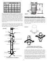
- Suitable lengths of chimney: The chimney diameter should be sized

to suit the appliance.

- Rain Cap: Standard or Deluxe model

To complete a proper Cathedral Ceiling Support installation, the
following parts are required:

CATHEDRAL CEILING SUPPORT (CCS)

- Cathedral Ceiling Support (CCS): For sloped or angled ceiling.
- Stove Pipe Adaptor (ASE): Transition from chimney to flue pipe.
- Roof Flashing Assembly: Required when the chimney penetrates
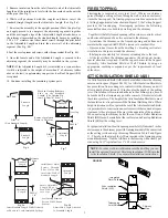
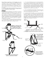
Chimney
Pipe

Tighten Bolt to
Secure Pipe

1/4” x 2”
Lag Bolts

Wall

Section

28. Place a length of chimney within the assembly and tighten the

tabs around the chimney using the supplied 1/4" x 2" bolt to secure

the chimney length within the band (See Figure 33).

27. Level the brackets and drill pilot holes in the wall using the

mounting holes in the brackets as a template.  Drill 1 hole in the wall

for each bracket.   Secure brackets to wall using 1/4" x 2" lag bolts

(see Figures 32 & 33).  Use a level against the chimey sections at

each support stage to keep the assembly plumb.

Figure 33

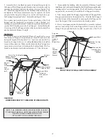
29. If the chimney penetrates an eave or overhang (soffit) cut an

opening with  2" clearance all around.  To find the exact spot where

the chimney will pass through the eaves, drop a plumb line from the

underside of the eaves to the outer edge of the leveled chimney.  Mark

5 or 6 points to give an outline of the hole.  Remember that the hole

will need 2" clearance to the chimney surface.  Install an Attic

Insulation Shield if space permits on the under side of the overhang.

If it is not possible, the overhang area can be enclosed and a Rafter

Radiation Shield installed at the roof  level and a Finishing Plate on

the underside of the soffit.  If the Attic is open to the overhang, close

off the access with suitable building materials ensuring that a 2" air

space clearance is maintained.   From above, install the Roof  Flashing

and Storm Collar by following the Roof Flashing section in these

instructions.  If the overhang is not deep enough to allow the chimney

to be fully installed within the overhang, it will be necessary to cut

into it. 


 Ensure that a 2"air space clearance all around the chimney

is respected.  Framing and flashing the sides of the opening will be

required.  Install a Wall Band at this level.

NOTE:  

Interior chimneys installed with a Wall Support must use

Firestop Radiation Shield (FRS) in place of Wall Bands if extending

through floor/ceiling penetrations and an Attic Insulation Shield

(AIS) when passing through an unoccupied attic space.

Содержание SUPERPRO SPR

Страница 1: ...MBUSTIBLE MATERIALS IT IS OF THE UTMOST IMPORTANCE THAT THIS CHIMNEY SYSTEM BE INSTALLED ONLY IN ACCORDANCE WITH THESE INSTRUCTIONS PLEASE READ ALL INSTRUCTIONS BEFORE BEGINNING YOUR INSTALLATION FAIL...

Страница 2: ...RESTOP RADIATION SHIELD INSTALLATION ELBOW INSTALLATION WALL SUPPORT INSTALLATION AWS INTERMEDIATE WALL SUPPORT AIWS WALL SUPPORT INSTALLATION WS WALL BANDS CATHEDRAL CEILING SUPPORT INSTALLATION RAFT...

Страница 3: ...3 SELKIRKCANADACORPORATION SELKIRKCANADACORPORATION 09 29 20 09 29 20 CERTIFICATIONLABELS...

Страница 4: ...udsistypicallyusedinthissituation Thespace betweentheouterwallofthechimneyandtheenclosuremustbealeast aminimumof2inches MAINTAIN A 2 MINIMUM AIR SPACE CLEARANCE BETWEEN INSULATED CHIMNEY SECTIONS AND...

Страница 5: ...ich can affect the operation and or performance of your appliance and or chimney system Plan your installation carefully If possible position the stove so that the flue outlet is between joists rafter...

Страница 6: ...nto the Decorator Ceiling Support and slide the assemblyintotheframedopeningfrombelow Ensurethatthefinishing ringisflushwiththeundersideofthefinishedceilingandtheassembly is level and plumb Secure the...

Страница 7: ...ler Up and apply pressure to compress the adjoining segments together until the overlapped edge of the Adjustable Length extends down to the reference line marked on the standard length Secure by inst...

Страница 8: ...ore securing into place When an Attic Insulation Shield is required above the Decorator CeilingSupportintoanatticasshowninFigure4 ensurethatthebase of the shield is flush with the top of the joist fra...

Страница 9: ...a ChimneyLengths mustpassverticallythroughframedjoistareas Two Story Basement Installation Attic Insulation Shield AIS Firestop Radiation Shield FRS Install an Elbow Support on the first Length just a...

Страница 10: ...ot cleanout section and or the Insulated Tee Plug which is installed below the support Figure 15 Installtheinteriorinnerhalf withroundplateandtabs ofthewallthimble into the inside wall opening ensurin...

Страница 11: ...hole Keep in mind the 2 clearance to the chimney outer surface Install an Attic Insulation Shield if space permits on the under side of the overhang If it is not possible the overhang can be enclosed...

Страница 12: ...oping adjustment from 4 1 2 to 8 3 4 2 For a non combustible wall concrete block or poured foundation cut a hole 3 16 greater in diameter than the outside diameter of the chimney as per Table 3 Break...

Страница 13: ...into the Tee branchbytwistingclockwise ALockingBandmustthenbeinstalled tosecuretheconnection Makesurethenutandboltarefacingdown to prevent any water from collecting in the Locking Band The Tee branch...

Страница 14: ...ew into the nutsert located on the front of the Support Plate see Figures 24 25 and 26 FIGURE 26 Securing of Insulated Tee Cap 14 Use a non hardening high temperature sealant 500 F to seal around the...

Страница 15: ...nstalltheInsulatedTeeCapasper step 15 20 It is required to have a Universal Wall Band UWB installed every 8 feet For systems shorter than 8 at least one Universal Wall Band UWB must be installed 21 Pl...

Страница 16: ...and by screwing four stainless steelsheetmetalscrewsthroughthedrawbandandintotheoutercasing CeilingTrimAngles CeilingTrimAngles Suitablelengthsofchimney Thechimneydiametershouldbesized to suit the app...

Страница 17: ...when exposed to windy conditions NOTE The male coupler of each chimney length must point up RAFTER RADIATION SHIELD RRS ARafterRadiationShield RRS mustbeinstalledwherethechimney is enclosed immediatel...

Страница 18: ...the seam of the cone where it meets the plate Apply a bead of silicone caulking along the back seam of the cone Assemble Chimney Sections through the roof opening and Flashing Ensurethatallsectionsar...

Страница 19: ...legs by sliding the supplied hose clamp over larger diameter leg and then inserting smaller diameter leg into larger diameter leg Temporarily hold legs together by tightening the hose clampoverthecut...

Страница 20: ...o telescoping legs should form an angle of about 60 to give support to the chimney in all directions The angle of the telescoping legs should be approximately 45 from vertical when fastened to the roo...

Страница 21: ...the heating season Where coal is burned the system must be thoroughly cleaned within 48 hours of shutting down the system for the season and all soot be removed from the chimney system This should be...

Страница 22: ...HIMNEY INSTALLATION It may be necessary to offset the chimney in order to clear a joist or an obstacle The three 3 charts below will assist you in selecting the proper combination of elbow angle and c...

Страница 23: ...bands at all joints for added safety and stability This will eliminate the risk of sections becoming undone below the roof line when the Rain Cap is removed when inspections and cleaning of the system...

Страница 24: ...Length 18 ChimneyLength 12 ChimneyLength 6 Chimney Length 12 Adjustable Length Tee with Plug Insulated Tee Cap 15o ElbowKit 30o ElbowKit 45 ElbowKit CeilingSupport WallSupport Kit Intermediate Wall Su...

Страница 25: ..._________________________________________________ DEALER INFO DEALER NAME _______________________________________________________ Address _____________________________________________________________...

Страница 26: ...SI QUE LA GARANTIE DU FABRICANT CONSERVEZ CES DIRECTIVES DANS UN ENDROIT S CURITAIRE AFIN DE POUVOIR VOUS REPORTER AU BESOIN UNE DES CAUSES PRINCIPALES D INCENDIES DE CHEMIN ES EST LE FAIT DE NE PAS M...

Страница 27: ...TALLATION DU COUPE FEU DE SOLIVE INSTALLATION DU COUDE INSTALLATION DU SUPPORT MURAL AWS INSTALLATION SUPPORT MURAL INTERM DIAIRE AIWS INSTALLATION DU SUPPORT MURAL WS BRIDES MURALE INSTALLATION DU SU...

Страница 28: ...3 SELKIRKCANADACORPORATION SELKIRKCANADACORPORATION 09 29 20 09 29 20 TIQUETTESDECERTIFICATION...

Страница 29: ...u elle soit encloisonn e sous la ligne du toit pour la prot ger contre les temp ratures froides ext rieures ceci pourrait r duire la condensation la formation de cr osote et am liorer le tirage Assure...

Страница 30: ...es en vous assurant que le d gagement sp cifi de 2 po 50mm aux combustibles soit maintenu Toutes les ouvertures devraient tre de forme carr e tre d aplomb et en alignement parfait avec chacune des aut...

Страница 31: ...sch mas 4 10 d montrent les deux types d installation les plus courantes pour un support de plafond d coratif Encadrer compl tement l ouverture carr e les 4 c t s selon les dimensions sp cifier au ta...

Страница 32: ...z l isolation du bout femelle de la longueur r glable jusqu ce que l isolation soit de niveau avec la ligne marqu e sur l ext rieur de la longueur sch ma 7 6 Tandis d tre toujours plac avec le bout m...

Страница 33: ...air libre entre le coupe feu solive FRS et la structure des solives TABLEAU D ENCADREMENT POUR LE PARE FEU POUR LE GRENIER DIAM TRE DE CHEMIN E OUVERTURE ENCADR E Tableau 2 Enclos Espace habit Solin...

Страница 34: ...alement par les zones de solives structur es Installation au sous sol pour deux tages cran thermique pour grenier AIS Coupe feu de solive FRS Chapeaudechemin e Placez le second coude coude de retour p...

Страница 35: ...longueurdechemin e install e pr c demmentsurlemanchondut danslabaguemuraleenvousassurantque l accouplement m le sur le t est vers le haut Ins rez et visez l anneau d ancrage dans le bout femelle du t...

Страница 36: ...et installez un coupe feu de solive L ouverture devra tre encadr et un coupe feu radiant install install auniveaudutoit Silegrenierestouvertausoffite fermezl acc savec des mat riaux de construction ap...

Страница 37: ...ouverture 3 16 po plus grande que le diam tre ext rieur de la chemin e selon le tableau 3 Cr er une petite ouverture pour confirmer que le trou sera centr entre les goujons et q aucuns fils lectriques...

Страница 38: ...l espace habit Serrez fermement dans le t en tournant dans le sens horaire Un collier de fixation doit tre install ce raccordement Assurez vous que l crou et le boulon font face vers le bas afin d em...

Страница 39: ...ort S curisez en place avec la vis de fixation dans le nutsert situ l avant de la plaque de soutien voir les sch mas 24 25 et 26 SCH MA 26 Fixation du bouchon de t isol 14 Employez un calfeutrant la s...

Страница 40: ...se tiennent ensemble Installez un collier de fixation pour prot ger en surplus les deux sections de chemin e Sch ma 30 Sch ma 31 Sch ma 32 Bande universelle Attache d espacement Trous pour boulon de...

Страница 41: ...de chemin e ad quates Le diam tre de la chemin e devrait avoir une dimension qui convient l appareil Chapeau de chemin e Mod le r gulier ou deluxe N B Pour r duire l infiltraion d air froid dans le l...

Страница 42: ...u radiant RRS doit tre install o la chemin e est enferm e imm diatement sous la ligne de toit tel que d montr au sch ma 39 Un exemple de ceci est quand l espace de grenier d une maison est employ en t...

Страница 43: ...chaque c t s en utilisant 12 clous avec rondelles en n opr ne ou couvrez les t tes de clous avec un calfeutrage imperm able l eau non durcissant appropri Scellez les bardeaux la plaque de la m me mani...

Страница 44: ...s syst me plus haut un secondaire peut treexig e F Assemblez les jambes t lescopiques en glissant la pince de serrage sur la jambe diam tre sup rieure et ins r e la jambe diam tre inf rieure dans cell...

Страница 45: ...t lescopiques devraient former approximativement un anglede60 pourdonnersupport lachemin edanstouteslesdirections Une fois fix au toit l angle des jambes t lescopiques ne devrait pas d passer 45 de l...

Страница 46: ...ann e Les entr es d air devraient tre ferm es et scell es au besoin pour emp cher l coulement constant d air dans le syst me AVERTISSEMENT NE PAS UTILISER DE MAT RIAUX COMBUSTIBLES CORROSIFS POUR L EN...

Страница 47: ...eurs n cessaires pour obtenir le degr d angle n cessaire dans une hauteur disponible 1 S lectionnez la colonne contenant le diam tre de votre syst me de chemin e 2 D terminez la distance requise pour...

Страница 48: ...fortement recommand d utiliser des colliers de fixation sur toutes les longueurs de chemin e pour une s ret et stabilit suppl mentaire lorsque expos s de forts vent au dessus du toit Ceci liminera au...

Страница 49: ...o Longueur ajustable 12po T et bouchon Bouchon de t isol Ensemble de coude 15o Ensemble de coude 30o Ensemble de coude 45 Support de plafond Supportmural Supportinterm diaire Supportmural Support cath...

Страница 50: ...ION _________________________________________________ INFORMATION DU D TAILLANT NOM DU D TAILLANT _________________________________________________ Adresse ____________________________________________...

Отзывы: