


17
Level
Roof
Pitch is 3/12
3"
12" Ruler
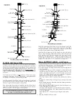
FIGURE 37
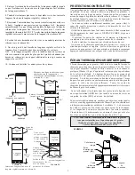
Roof Pitch Calculation
Find the centre of the opening by dropping a plumb bob from the
inside of the roof sheathing to the centre of the leveled chimney
length below. Do the same to find the outline of the required opening
to the edge of the hole in the ceiling below. By moving the plumb
bob around the edge of the opening below (which includes the
required clearance) mark several points forming the outline of the
hole on the underside of the roof sheathing. Remember: these
measurements are in the horizontal plane. Drill pilot holes following
the marked outline.
Once you have marked and located the area where the chimney will
come through the roof, center, position and prepare the roof area by
removing shingles, shingle nails and cutting of the roofing material.
Be careful when lifting roof shingles so they do not become damaged
as they may be old or if the installation is done during cold weather.
Frame the opening to suit the pitch of the roof and allowing for a 2"
clearance to the chimney on all four (4) sides. This is done before
extending the chimney above the roof.
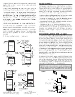
Ensure that you have the proper Roof Flashing by checking your roof
pitch using a level and two rulers (see fig. 37) or by using a roof pitch
card.
The AAF Roof Flashing is for roof pitches from 0/12 to 6/12.
The AF2 Roof Flashing is for roof pitches from 6/12 to 12/12.
ROOF FLASHING
Slide the Roof Support down over the chimney section until the
support brackets rest on the roof or floor. Use a level against or on
top of the Chimney Length to ensure that the chimney is plumb
prior to the final position of the support brackets. Tighten the
support band around the chimney with the nuts and bolts supplied,
then secure the collar by screwing the 6 supplied sheet metal screws
through the holes in the support band and into the chimney casing.
Center the chimney in the joist or rafter opening (ensure that the 2"
required air space clearance is met) and nail or screw the Roof Support
to the roof or floor using the 12 x 3-1/2” spiral nails supplied or 12 #8
x 2" wood screws into a solid base.
Install additional Chimney Sections and lock together by turning
clockwise until the two sections lock together tightly - continue in
this manner until the desired height is achieved. The use of Locking
Bands on all Chimney Lengths above the roof is highly recommended
for added safety and stability when exposed to windy conditions.
NOTE:
The male coupler of each chimney length must point up.
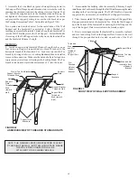
RAFTER RADIATION SHIELD (RRS)
A Rafter Radiation Shield (RRS) must be installed where the chimney
is enclosed immediately below the roof line as shown in
figure 26. An example of this is when the attic space of a house is being
used as living space (ie. bedroom, guestroom etc.). It must also be
installed when height restrictions will not allow the use of the Attic
Insulation Shield (AIS) and the chimney has been enclosed with an
enclosure around the chimney.
Attach the support brackets to the shield (through one of the three
pre-punched holes) such that once the shield is installed, the shield
protects both the upper and lower parts of the roof joist framing (See
figures 35 & 39).
Rafter Radiation Shield Assembly
FIGURE 35
Shield
Bracket
Screw
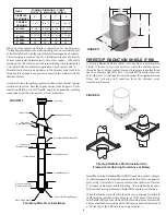
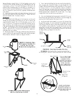
ROOF SUPPORT (RS)
The Roof Support may be used on a floor, ceiling or roof and adjusts
to any roof pitch. It may be used above an offset to support the offset
or as a supplementary support when the chimney height exceeds that
of the primary support. It will also provide additional support for a
Cathedral Ceiling installation when more than 3 feet is above the roof.
The Roof Support will support a total height of 50 feet of chimney
sections of which 20 feet may be suspended beneath it. All chimney
sections below the support must be secured with Locking Bands.
The Roof Support is mounted directly on the roof sheathing with
FIGURE 36
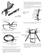
Roof Support Assembly
Nut
Lock Washer
Support Band
Carriage Bolt
Support
Bracket
Attach the support brackets to the support band with the 1/2” nuts,
bolts and lock washers. The lock washer is placed between the band
and support bracket to provide proper spacing as shown in Figure 27.
7. 4 painted ceiling trim angles (2 short & 2 long) are supplied with
fastening screws to finish off the Support Box at the ceiling level. The
2 long pieces are trimmed off to match the pitch of the ceiling.
its feet (support bracket) resting over rafters or a framed opening to
form a solid base. Frame a rectangular roof opening to provide a 2"
minimum air space clearance from combustible materials. The framing
dimension is measured in the horizontal plane.
6. Chimney sections (15 ft max.) installed below the Cathedral Ceiling
Support are locked together from below by turning clockwise until
tightly locked together with each joint being secured by a Locking
Band.These lengths can be painted to match the connector pipe with
a high temperature heat resistant paint. To improve adhesion to the
chimney, degrease, clean, prime before painting. Follow the paint
manufacturer's instructions.


