


12
2
2.5
3
3.5
4
4.5
5
5.5
6
74
73
71
69
66
62
58
52
45
63
62
60
59
56
53
50
45
39
56
55
53
51
49
46
43
38
34
49
48
47
46
44
42
39
35
30
7-3/16"
8-3/16"
9-3/16"
10-3/16"
14-3/8"
5"
6"
7"
8"
9-1/4"
9-1/4"
10-1/4"
11-1/4"
A
B
A
B
Section
14-3/8"
14-3/8"
14-3/8"
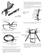
3. After framing in your opening to the dimensions specified to the
Framing Tables 1 or 3, install the outer half (with the unfinished square
plate) of the Wall Thimble into the outside wall opening. Secure in
place with appropriate fasteners through the pre-punched holes.
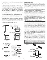
NOTE:
To reduce cold air infiltration into the dwelling you
can install the optional Universal Shielding Insulation (JUSI)
into the Wall Thimble. See separate installation instructions
packaged with the JUSI.
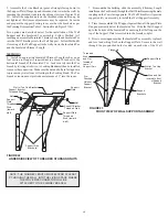
4. Install the inner half (with round plate) of the Wall Thimble into the
inside wall opening, ensuring that the shield slides over the shield of
the outer half. Once in place and flush against the wall, install the black
finishing trim plate onto the wall surface and fasten in place with ap-
propriate fasteners through the 4 pre-punched holes.
Wall Thimble
Black
Finishing
Round Plate
Interior Inner
Half of Wall
Thimble
Exterior Outer
Half of Wall
Thimble
Figure 20
Telescoping adjustment from
4-1/2” to 8-3/4”
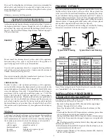
2. For a non-combustible wall (concrete block or poured
foundation), cut a hole (3/16”) greater in diameter than the outside
diameter of the chimney as per Table 3.
- Break out part of the wall covering within the outline to confirm that
the hole will be centered between studs and that no electrical wires
could be cut by the saw.
outline of the hole and drill a pilot hole in its center.
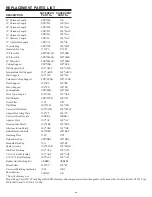
Distance
from Wall
to Chimney
5” ID
Chimney
6” ID
Chimney
7” ID
Chimney
8” ID
Chimney
H(feet)
Max. Height
H (feet)
Max. Height
H (feet)
Max. Height
H (feet)
Max. Height
D (inches)
Wall/Chimney
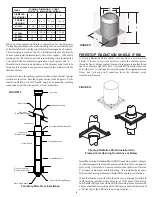
Table 4 - Wall Support Chimney Height Chart
Table 3 -
Framing Dimensions
Wall Thimble & Support Brackets
Wall Thimble
Minimum Framed Opening
for Combustible Wall
Minimum Round Hole
Diam. For Non-Combustible Wall
Support Brackets
Minimum Framed Opening
For Bracing
Chimney Size (ID)
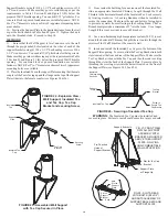
FIGURE 19
Rain Cap
Storm Collar
Wall Band
Locking Band
Insulated Tee
8 Feet
(Max)
3" Minimum
Chimney Section
Stove Pipe Adaptor
Wall Thimble Inner Half
Wall Thimble Outer Half
Ventilated Flashing
Support Bracket
Support Plate
Lag Screws into Structure
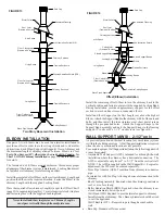
Figure 21
"D"
Distance
from Wall to
Chimney
(2" minimum
or as per
Table 4)
"H"
Max.
Chimney
Height
(See Table 4)
D
- Distance from wall to the chimney
H - Height of chimney in feet
See Figure 10 also.
See Table 4 for maximum Chimney Heights based on
Chimney Diameter and Distance from Wall


