


20
CHIMNEY FIRES AND WHAT TO DO ABOUT THEM:
Your Model JM/ALT chimney is not intended or designed for use as
a combustion or fire chamber. It is very easy to overfire your
woodburning appliance with kindling, scrap lumber, brush or any fast
burning fuel. This can produce flames and high temperatures all the
way up the chimney, and may cause appliance and chimney damage.
If you see your appliance or the flue pipe glowing red, you are risking
chimney damage or a fire. The creosote may be burning inside the
chimney. If you see flames coming out at the top, you are either
overfiring or there is a chimney fire.
If the fire in your appliance has gotten out of control, or if you suspect
a chimney fire for any reason, follow these steps:
1. Immediately close all dampers and/or air entrance openings to
your appliance. Block off fireplace openings.
2. Alert your family to the possible danger.
3. Inspect your appliance and chimney surroundings for possible
fire. If in doubt, alert your Fire Department.
4. Do not continue to operate your appliance until it and your
chimney have been thoroughly inspected. Overheating can cause
metal parts to expand, buckle and crack. If you are not certain, have
a certified wood technician or certified chimney sweep disassemble
all parts so they can be inspected and replaced.
5. Do not use salt or water on the fire in your appliance. Salt is
corrosive and water will cause a dangerous steam explosion. You
might be able to control the fire by using ashes, sand or baking soda.
Baking soda is an ingredient used for dry chemical fire extinguishers.
6. After a chimney fire, when it is safe to do so, check internal
locations such as the attic and under the roof and keep watching for
two or three hours. There may be delayed smoldering and subse-
quent ignition, even if the fire inside the chimney has been controlled.
WARNING:
DO NOT USE FUEL MATERIALS CORROSIVE TO THE
CHIMNEY LINER SUCH AS DRIFTWOOD, PLASTICS,
CHEMICALLY TREATED WOOD, ETC.
Contact a professional certified chimney sweep for chimney clean-
ing services and advice if you have any doubt about your ability to
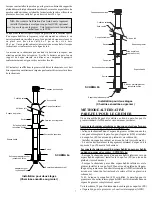
clean your chimney system or if the task is too large. Tovisually
inspect the chimney, remove the Rain Cap by simply using the twist-
lock feature. Care should be taken not to disengage any lower
chimney sections. By removing the Rain Cap this will permit the
insertion of a properly sized plastic chimney cleaning brush. A metal
brush may scratch the liner and lead to premature corrosion. The
Insulated Tee Cap (if so equipped) can be removed by twisting anti
clockwise or by removing the securing bolt and sliding the Tee Cap
Bracket out. Be sure to replace the Rain Cap and the Tee Cap or
Insulated Tee Cap, Tee Cap Bracket/Securing Bolt once you have
completed inspecting and cleaning the chimney.
If chemical cleaner is used to assist in the cleaning of your chimney,
make sure it is a product which is non corrosive. It does not replace
the need for a mechanical cleaning. The optimal method for cleaning
a chimney is by a mechanical brushing of the chimney in conjunction
with a complete evaluation of the system by a certified chimney
sweep.
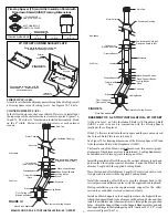
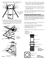
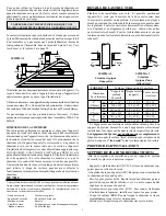
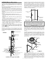
Adapter Plate (AP)
ADAPTER PLATE (AP) - MASONRY FIREPLACE
The Adapter Plate (AP) is intended for use with a masonry fireplace
with model JM/ALT chimney. The Adapter Plate (AP) provides a
connection from a masonry fireplace to Model JM/ALT insulated
chimney. Refer to the following section in these instructions to
complete your installation to a masonry fireplace:
- Pre-Installation Guidelines
- Framing Details
- Stove Pipe Adapter
- Attic Insulation Shield
- Elbow Installation
- Roof Support
- Roof Flashing
- Universal Roof Guy Kit
The following steps describe the installation the the Adapter Plate
and the above mentioned sections of these instructions are to be
followed.
1. Mount four (4) 1/4" diameter bolts, 3" long securely into the top
of the masonry fireplace around the outlet opening. Use the 4 holes
on the Adapter Plate as a template to located the placement of these
bolts.
2. Apply a bed of mortar approximately 3/4" in depth and 3" in width
completely around the outlet opening. Make sure the threaded ends
of the bolts protrude a minimum of 1" above the bed or mortar.
3. While the mortar is still damp, place and level the Adapter Plate
over the extended studs. Secure using a washer and nut for each bolt.
4. Check the Adapter Plate for level and allow mortar to set.
5. Place a section of chimney and lock it onto the Adapter Plate by
turning clockwise until the section lock snugly. Up to 40 feet of
chimney may be stacked on the Adapter Plate.
Ensure you obtain any necessary building permits and that your
installation will conform with all federal, provincial, municipal
installation and fire codes for all requirements affecting your instal-
lation. Check with your local building code for masonry fireplace
requirements.


