


16
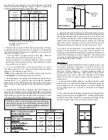
ROOF FLASHING
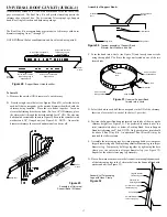
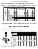
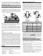
Ensure that you have the proper roof flashing by checking your roof
pitch using a level and two rulers (see fig. 25) or by using a roof pitch
card.
The AAF flashing is for roof pitches from flat to 6/12.
The AF2 flashing is for roof pitches from 6/12 to 12/12.
Level
Roof
Pitch is 3/12
3"
12" Ruler
FIGURE 25
Roof Pitch Calculation
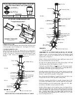
Find the centre of the opening by dropping a plumb bob from the
inside of the roof sheathing to the centre of the leveled chimney
length below. Do the same to find the outline of the required opening
to the edge of the hole in the ceiling below. By moving the plumb bob
around the edge of the opening below(which includes the required
clearance) mark several points forming the outline of the hole on the
underside of the roof sheathing. Remember: these measurements are
in the horizontal plane. Drill pilot holes following the marked
outline.
Once you have marked and located the area where the chimney will
come through the roof, center, position and prepare the roof area by
removing shingles, shingle nails and cutting roofing material. Be
careful when lifting roof shingles so they do not become damaged as
they may be old or when the installation is done during cold weather.
Frame the opening to suit the pitch of the roof and allowing for a 2"
clearance to the chimney on all four (4) sides. This is done before
extending the chimney above the roof.
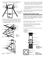
Shingles
Flashing
Nails
Roof Flashing Installation
FIGURE 26
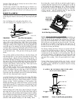
Apply a bead of
silicone caulking
along the seam of
the cone where it
meets the plate
Apply a bead of
silicone caulking
along the back
seam of the
cone
Nail the flashing to the roof deck (also under the shingles) along the
upper edge and down each side with 12 nails with neoprene washers
or cover the nails with a suitable non hardening waterproof caulking.
Seal the shingles to the plate in the same manner. As a precaution, you
may apply a bead of caulking along all seams of the flashing. Wrap
the Storm Collar around the chimney above the flashing. Secure
NOTE: A Rubber Boot Flashing Kit (URBFK2)
is available as an
option for passing through a corrugated or metal roof. See separate
instructions packaged with the Rubber Boot Flashing Kit. On metal or
steep roofs, it is recommended that an ice deflector or chimney cricket
fabricated from heavy guage galvanized steel be installed. The wedge-
shaped deflector is installed 2" from the chimney on the upper slope. Its
function is to split ice and snow as they slide down the roof, preventing
damage to the chimney and flashing.
The chimney, Flashing and Storm Collar may be painted with a heat
resistance rust proofing paint when enclosing of the chimney is not
possible or if exposed to wind driven ocean spray. Salty humid air
causes metal to corrode faster than air with normal humidity. This will
extend its life and improve the appearance and could be matched with
the roof shingles. To improve adhesion to the chimney, degrease, clean
and prime before painting. Follow the paint manufacturer's instruc-
tions.
Continue adding chimney lengths until the proper height is achieved
(see Figure 1). Install locking bands at all chimney joints above the roof
for added protection. Install the rain cap and lock it in place by turning
clockwise until snug.
NOTE: Slide the top edge (nearest to the roof peak) of the flashing
under the roofing shingles. At least half of the flashing should be
UNDER the shingles and the bottom edge OVER the shingles to
provide a watershed. Trimming off the shingles may be neccessary
around the cone of the flashing for a better fit. Do not nail the flashing
to the roof yet as adjustments may be required.
Assemble Chimney Sections through the roof opening and Flashing.
Ensure that all sections are locked together by turning clockwise
until the sections lock snugly. Install Locking Bands to secure the
chimney sections. Before committing to a final position of the
Flashing and chimney, ensure the entire Chimney system is level and
plumb and the required 2" air space clearance is maintained from all
combustible materials before permanently nailing and sealing of the
Flashing to the roof.
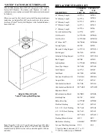
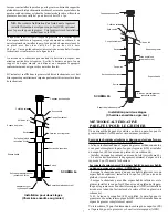
WARNING: DO NOT BLOCK THE VENTILATION
SLOTS ON THE FLASHING.
Ventilation Slots
Rain Cap
Enclosure
Rafter Radiation
Shield
Flashing
Storm Collar
FIGURE 27
Storm Collar/Flashing Installation
the ends together loosely with the nut and bolt supplied. Apply a
non-hardening high temperature silicone caulking just above the top
of the flashing cone on the chimney outer shell. Slide the collar down
the chimney until it contacts the flashing cone and into the caulking.
Tighten the nut and bolt and apply additional caulking above the Storm
Collar as required. After the installation check to ensure that the
ventilation slots are not obstructed (see Figure 26).
Attach the support brackets to the shield (through one of the three pre-
punched holes) such that once the shield is installed, the shield protects
both the upper and lower parts of the roof joist framing (see Figures 24
& 27).
Insulation Shield (AIS) and the chimney has been enclosed with an
enclosure around the chimney.


