


14
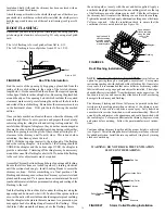
WARNING:
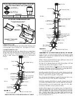
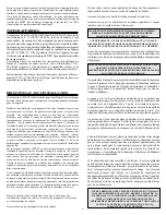
The Insulated Tee Cap must be installed and secured
in place. Failure to install could cause fire, injury or death.
Insulated
Chimney
Sections
Support
Plate
Insulated Tee Cap
Nutsert
Screw to
Secure Tee
Cap Bracket
Tee Cap
Bracket
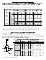
15. Insert the Insulated Tee Cap into the bottom of the Support Plate
opening and secure by sliding the Tee Cap Bracket into both slots
located at the front and rear of the Support Plate. Make sure the Tee
Cap Bracket is beneath the Tee Cap and the other end is exiting
through the slot at the back of the Support Plate. Secure in place by
threading the securing screw into the nutsert located on the front of
the Support Plate (Figures 16, 17 and 18).
FIGURE 18 - Securing of Insulated Tee Cap
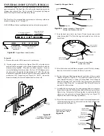
14. Use a non-hardening high-temperature sealant (500
°
F) to seal
around the horizontal Chimney Length where it enters through the
exterior of the Wall Thimble or the concrete wall.
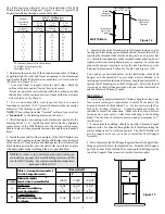
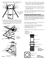
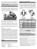
Nuts
Slot on
Support
Bracket
Support Brackets
Pre-Punched
Holes of Support
Bracket
Support Plate
w/ Flange Up
Slot for Tee Cap
Bracket
Slot on
Support
Plate
Bolts
FIG. 20- SLOT AREAS
WITH BOLTS (#8 x 3/4")
AND NUTS ASSEMBLY
OF SUPPORT BRACK-
ETS AND SUPPORT
PLATE
FIG. 19- FRONT VIEW
OF WALL SUPPORT
ASSEMBLY WITH
BRACKETS MOUNTED
ABOVE THE SUPPORT
PLATE - ONLY IN A NON-
COMBUSTIBLE WALL
APPLICATION
17. For lateral stability of the chimney above the Wall Support (
either AWS or WS), a Wall Band must be installed along an outside
wall. Install the first Wall Band midway up the first Chimney Length
above the Insulated Tee and any additional Wall Band to be installed
at 8 foot intervals above this point. Secure the Wall Band bracket
to the wall using 2 6d (2") spiral nails or #8 x 2" wood screws through
the pre-drilled holes (see Figure 21). For concrete or brick veneer
walls, use suitable masonry fasteners or other anchoring systems.
18. Fasten securely the Wall Band around the chimney with the
supplied nut and bolt. Check for clearances and plumb as you fasten
the Wall Bands to the wall. Use a level against the chimney sections
at each support stage to keep the assembly plumb.
19. If the chimney penetrates an eave or overhang (soffit) cut an
opening with 2" clearance all around. To find the exact spot where
the chimney will pass through the eaves, drop a plumb line from the
underside of the eaves to the outer edge of the leveled chimney.
Mark 5 or 6 points to give an outline of the hole. Remember that the
hole will need 2" clearance to the chimney surface. Install an Attic
Insulation Shield if space permits on the under side of the overhang.
If it is not possible, the overhang area can be enclosed and a Rafter
Radiation Shield installed at the roof level and a Finishing Plate on
the underside of the soffit. If the Attic is open to the overhang, close
off the access with suitable building materials ensuring that a 2" air
space clearance is maintained. From above, install the Roof
Flashing and Storm Collar by following the Roof Flashing section in
these instructions. If the overhang is not deep enough to allow the
chimney to be fully installed within the overhang, it will be necessary
to cut into it.
Ensure that a 2"air space clearance all around the
chimney is respected. Framing and flashing the sides of the opening
will be required. Install a Wall Band at this level.
NOTE:
Interior chimneys installed with a Wall Support must use an
Attic Insulation Shield (AIS) when extending through floor/ceiling
joist and into attic space.
Wall Band
Figure 21
NOTE:
If ground clearance does not permit the installation of the Wall
Support with the Support Bracket facing down, it is permissible to
invert these brackets, if in a non-combustilbe wall application. Invert-
ing the brackets (brackets mounted on the wall above the support
plate) can be accomplished by rotating the Support Plate so that the
threaded stud faces toward the front and securing each side with (2) #8
x 3/4" bolts (not supplied) through the oblong slots of the support side
brackets and the support plate as per Figures 19 and 20. Secure with
nuts. In this position, the range of adjustability is limited to 5” from
the wall. Install the Insulated Tee Cap as per step 15.
To complete a proper Cathedral Ceiling Support installation, the
following parts may required:
- Cathedral Ceiling Support (CCS): To support chimney with a
sloped ceiling
- Stove Pipe Adaptor (ASE): Transition from the chimney to flue
pipe.
- Universal Shielding Insulation (JUSI): To reduce cold air infiltra-
tion into the dwelling when installed in conjunction with the
Cathedral Ceiling Support.
- Roof Flashing Assembly: Required when the chimney penetrates
a roof.
- Suitable length(s) of chimney: The chimney diameter should be
sized to suit the appliance.
- Rain Cap: To prevent rain and/or debris from entering into the
chimney. Standard or Deluxe model.
CATHEDRAL CEILING SUPPORT (CCS)
16. Chimney Lengths above the Insulated Tee are simply stacked
on and locked with a 1/8 clockwise turn.
Wall Band (WB)


