background image

Safety

Ausgabe 
issue 

B / 21.04.1999 

Dokument 
document 

OM.SAF.01e 

Blatt 
sheet 

1 (2) 

2.0 
Safety 
 

These operating instructions contain basic require-
ments to be observed during the installation, opera-
tion and maintenance of the machine. Therefore, the 
instructions must be read by the mechanical fitter and 
by the technical personnel/operator responsible for 
the machine prior to assembly and commissioning, 
and kept available at the operating site of the 
machine/plant at all times. 
 
Compliance is required not only with the general 
safety instructions given in this section but also with 
the detailed instructions, e.g. for private usage, given 
under the other main headings in these operating 
instructions. 
 

2.1 
Labeling of Advice in the Operating Instructions 
 

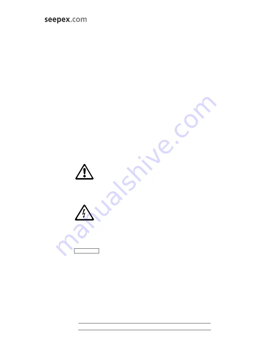
In these operating instructions safety advice whose 
non-observance could lead to danger for life or limb is 
labeled with the following general hazard symbol: 

safety symbol acc. to ISO 3864 - B.3.1 
 
Warnings regarding electric power are labeled with: 

safety symbol acc. to ISO 3864 - B.3.6 
 
Safety instructions whose non-observance could 
jeopardize the machine and its functions are labeled 
by the word 


CAUTION 

Always comply with instructions mounted directly on 
the machine, e.g.  
- rotational direction arrow 
- fluid connection indicators 
 
and ensure that the information remains legible.


2.2 
Personnel Qualifications and Training 
 

Personnel charged with operation, maintenance, 
inspection and assembly must be in possession  
of the appropriate qualifications for the tasks.  
The company operating the machine must define 
exact areas of responsibility, accountabilities and 
personnel supervision schemes. Personnel lacking 
the required skills and knowledge must receive 
training and instruction. If necessary, the opera-ting 
company may commission the manufacturer/ 
supplier to conduct these training courses. Further-
more, the operating company must ensure that the 
personnel fully understand the contents of the 
operating instructions. 
 

2.3 
Dangers Resulting from Failure to Observe 
Safety Instructions 

 
Failure to comply with the safety instructions may 
lead to hazards to life and limb as well as dangers 
for the environment and the machine. Non-obser-
vance of safety instructions can invalidate the right of 
claim to damages. 
 
The following are just some 

examples

 of possible 

dangers resulting from failure to comply with the 
safety instructions: 
 
- Failure of important machine/plant functions 
 
- Failure of prescribed methods of service and 

maintenance 

 
- Danger to life and limb due to electrical, 

mechanical and chemical influences 

 
- Danger to the environment due to the leakage  

of hazardous substances 


2.4 
Safety-conscious Working 

 
Always comply with the safety instructions listed in 
this document, the existing national accident 
prevention regulations and any company-internal 
work, operating and safety rules. 
 

6

Содержание BW 10

Страница 1: ...e size BW 10 commission No 822812 Job 2109552 This operating and maintenance instruction includes important safety information and instructions for installation commissioning operation and maintenance of the seepex machinery It is essential therefore that the responsible ...

Страница 2: ...irective 1 2 7 1 Manufacturer s Declaration seepex Manufacturer s Declaration as required by the EEC Machine Directive 89 392 EEC Appendix II B The seepex machines delivered in accordance with our design are intended to be fitted in one machine or assembled together with other machines to form one machine plant The commissioning of the machine is forbidden until such a time as has been established...

Страница 3: ...achine 1 2 10 Technical Data Sheet see Point 9 1 2 11 Performance Data Load Index Power Consumption are indicated in the associated data sheet Point 9 1 2 12 Sound Pressure Level The sound pressure level and or noise characteris tics of the seepex machines are ascertained in accordance with DIN 45635 The measuring guidelines are largely identical with the international standards ISO 3740 1980 and ...

Страница 4: ...s legible 2 2 Personnel Qualifications and Training Personnel charged with operation maintenance inspection and assembly must be in possession of the appropriate qualifications for the tasks The company operating the machine must define exact areas of responsibility accountabilities and personnel supervision schemes Personnel lacking the required skills and knowledge must receive training and inst...

Страница 5: ...iently familiar with the machine As a basic rule the machine must be brought to a standstill before work is carried out Always comply with the de commissioning procedure described in this document Any machines or assemblies conveying media that are detrimental to health must be decontaminated Immediately following completion of work all safety and protective devices must be replaced in position an...

Страница 6: ...on notices and symbols 3 4 Intermediate Storage Preservation Unless otherwise indicated in the data sheet seepex machines are provided with preservation only for the duration of transport If a long period of intermediate storage is foreseen before the machine is commissioned it is necessary to pro vide supplementary preservation If necessary the appropriate measures should be drawn up in consultat...

Страница 7: ...ide in every position of the eccentric screw even when the pump is stationary The pump owes its high suction capacity to this sealing between the suction and pressure sides 4 2 Mechanical Design Please consult the sectional drawing Point 9 for the mechanical design of the pump The data sheet Point 9 gives information on the design of the pump housing stator rotor and rotating components Refer to d...

Страница 8: ...g stator construction dimensions 5 3 Stator construction dimensions P Refer to the dimensional drawing 5 4 Erection of the complete mounted pump Erect in accordance with technical data Chapter 3 0 Heed dimensional drawing Tension free mounting of the pump Balance unevenness with suitable supports Applies to mounting on foundations load bearing elements Total areas of all pump bearing areas are res...

Страница 9: ... for the position nominal pipe size and norm Heed rotational direction direction of flow 5 6 2 Dimensioning of pipe work Adhere to specifications regarding pressure in the pressure or suction connection Heed technical data Chapter 3 0 Nominal pipe size of suction pipe nominal pipe size of suction connection of pumps 5 6 3 Residue free pipe work NOTICE Damage to property through assembly residue No...

Страница 10: ...uent operation of the pump is self priming even if an air column up to the liquid level remains 6 2 4 Electric Hydraulic Connections The connections are listed in the appended manufacturer s documents Point 10 The risk of exposure to electrical hazards must be ruled out Always observe the safety regulations valid at the site of installation 6 2 5 Checking Direction of Rotation The rotational direc...

Страница 11: ...tion between rotor and stator quickly causing an unacceptably high temperature to develop on the inner surface of the stator This overheating leads to burning of the stator material and the total failure of the pump For this reason it is necessary to ensure that the suction sided flow never dries up completely If a continuous flow cannot be guaranteed for the plant it is essential to fit the seepe...

Страница 12: ...side or shut off directly behind the pump connections Drain any residual liquid in the pump casing by opening removing the screwed sealing plugs 705 and 502 sealing rings 706 and 503 Casings without screwed plug must be evacuated by the connection branch SAG and DRS Refer to the data sheet and the sectional drawing of the associated operating instruction Point 9 for information on the pump design ...

Страница 13: ...of energy Secure electrical connections against restarting Empty pipes Allow pipes to cool down Remove pipe connections suction side pressure side Heed decommissioning Chapter 6 _ 9 1 2 Demontage WARNING Tilting or falling pump Injuries and or damage to equipment Death or serious injury can result Secure the pump 9 1 2 1 Druckstutzen 700 Demontage Dismantle pressure branches 700 602 606 604 700 9 ...

Страница 14: ... from plug in shaft 307 Dismantling of joint G Rotating unit individual parts Chapter 9_ 600 307 G 9 1 2 5 Mechanical Seal SEA dismantling Detasch set screws 378 Dismantle set collar 372 Mechanical seal SEA and mechanical seal retainer 333 Dismantle shaft sealing Chapter 9 _ SEA 378 372 333 9 1 2 6 Plug in Shaft 307 dismantling Tool W26 assembly mandrel Remove plug in shaft pin 309 from plug in sh...

Страница 15: ... 1 Plug in Shaft 307 reassembly Clean the flange mechanism surfaces FLS and output pivots of the drive ANT FLS ANT Slide on plug in shaft 307 Tool W26 assembly mandrel Insert the plug in shaft pin 309 into the plug in shuft with tool W26 309 307 W26 9 1 3 2 Mechanical Seal SEA reassembly Tool W27 Mounting sleeve with assembly mandrel Gleitringdichtungs Aufnahme 333 Gleitringdichtung SEA und Stellr...

Страница 16: ... pressure casing 500 water level SH 500 501 212 210 600 9 1 3 5 Stator 601 reassembly Support rotor 600 with base S to prevent it falling down Add lubricant liquid soap to the opening on the pressure branch side between the rotor 600 and stator 601 Turn rotor 600 in the right rotating direction Add lubricant liquid soap to the opening on the pressure branch side between the rotor 600 and stator 60...

Страница 17: ...ive goggles Detach holding band strap SCL Use suitable tool WM Push out strap part of holding band SCL Remove holding band 406 407 9 2 1 2 Universal joint sleeve 405 dismantling Pull back universal joint sleeve 405 9 2 1 3 Retaining sleeve 401 dismantling Knock back retaining sleeve 401 Use suitable tool WM 9 2 1 4 Detach joint Eject coupling rod pins 402 Remove Rotor 600 Tool W5 Drift Knock guide...

Страница 18: ... W4 9 2 3 Rotating unit RTE individual parts reassembly HINWEIS Faulty functioning of joints Malfunctioning and or destruction of joints Damage to property may result Replace the coupling rod pins 402 and guide bushing 403 jointly 9 2 3 1 Rotor 600 Plug in shaft 307 reassembly Slide the universal joint sleeve 405 onto the Rotor 600 Fill the joint head with seepex joint grease Side on retaining sle...

Страница 19: ...displaced manner 2x180 Use suitable tool WK Tool W15 Mounting plate Remove tool W15 9 2 3 3 Universal joint sleeve 405 reassembly Moisten the surface of the coupling rod 400 interior of the universal joint sleeve 405 with joint grease maintenance Chapter 7 0 Slide on the universal joint sleeve 405 Vent the inside area of the joint Use suitable tool WS Assemble holding band Holding band assembly Ch...

Страница 20: ...end of holding band with control lever EX turn crank KU until the holding band is strained and fitting against the holding band loop SCL Carefully contract holding band until it fits inside the circular groove of the universal joint sleeve Correct holding band tension HBD Correct Holding band HBD has slightly con tracted outer form of univers al joint sleeve and is stuck in position Incorrect Hold...

Страница 21: ...the universal joint sleeve may occur Shearing off holding band HBD made of Hastelloy C The high strength of this material makes it impossible to shear off the holding band HBD with the cutting lever SH Once the end of the holding band is folded back cut off the holding band HBD file off projecting edges and remove burr Check after mounting of holding band The holding band must run all the way roun...

Страница 22: ...shaft is misaligned to drive Check whether coupling gear is worn Realign coupling The coupling gear has perhaps to be replaced X X k Speed too low Increase the speed when high suction performances are required and when the liquid is very thin X X X l Speed too high Reduce the speed when pumping products with high viscosities danger of cavitation X m Check the axial play in the coupling rod linkage...

Страница 23: ...Auxiliary seepex documentation Ausgabe issue A 03 05 1995 Dokument document OM ACC 01e Blatt sheet 1 1 9 0 Auxiliary seepex documentation 25 ...

Страница 24: ...x conveying capacity 5000 L h pump speed 541 rpm press in press branch 2 bar press in suct branch assumed flooded differential pressure 2 bar operating torque 18 lb ft required drive power 96 Hp starting torque 12 lb ft remarks technical pump data range BW kind of install horizontal size 10 direction of rot clockwise pressure stage 0 pos of branch 1 component material design option suction casing ...

Страница 25: ...07A4 frequency 60 Hz special electric motor manufacturer Baldor voltage 3 X 575 VAC nominal power 5 Hp rated frequency 60 Hz mounting position B3 B14 protection TEFC starting Direct on freq inverter thermal class F special IEC face Super E model number 6 pole motor Baldor 37L860Y762G1 painting execution standard color RAL 5013 blue remarks packing packing type Skid marking 2109552 documentation di...

Страница 26: ......

Страница 27: ......

Страница 28: ......

Страница 29: ...tte universal joint sleeve manchette 1 406 Halteband holding band collier de serrage 1 407 Halteband holding band collier de serrage 1 500 Druckgehäuse pressure casing carter de refoulement 1 501 Gehäusedichtung casing gasket étanchéité du carter de refoulement 1 502 Verschlussschraube casing gasket étanchéité du carter d aspiration 1 503 Dichtring screwed plug bouchon de vidange 1 600 Rotor rotor...

Страница 30: ......

Страница 31: ...press counter ring with o ring into mecha nical seal housing 333 To facilitate assembly the o ring should be moistened with a lubricant diluted fluid soap ATTENTION Oil or grease must not be used to facilitate assembly Install mechanical seal housing 333 to lantern 200 and onsure correct position of flushing connections Remove plug in shaft 307 burrs and roughness and clean the unit Check adjust s...

Страница 32: ......

Страница 33: ...ing parts set of gaskets Item number acc to sectional drawing of pump and parts list Part designation Number Rotor 1 600 Stator 1 1 601 Universal joint sleeve 1 405 Coupling rod pin 1 402 Holding band small 1 2 1 407 Holding band big 1 1 406 Casing gasket 1 501 Sealing ring 1 503 Mechanical seal 1 330 Flushing ring 1 310 Plug in shaft 1 307 Special joint grease 098 1 cart 300 gr c 315cm grease qua...

Страница 34: ...008 0 A2619 2 24 2 12V 5 12 8 12T 10 6L 15 6LT 05 48 DHS XX 050 0000 0 A2620 BLZ XX 020 0010 0 A2619 5 24 5 12V KRZ XX Z55 0250 0 00000 KEZ XX Z55 0250 0 00000 10 12 17 6L 30 6LT 15 12T 10 24R 1 48 PKZ XX 000 0000 0 XOHV0 DHS XX 100 0000 0 A2620 BLZ XX 020 0010 0 A2619 14 12 26 6L 40 6LT 10 24 10 12V 17 12 35 6L 26 12 52 6L 55 6LT 75 6LT 30 12T 10 24 17 24R 2 48 DHS XX 120 0000 0 A2620 BLZ XX 025 ...

Страница 35: ...2 6L 1 24 1 12V 2 12 5 6L MTD L2 060 0020 0 XXXXX MTH M8 060 0020 0 XXXXX AZV B2 262 0020 0 XXXXX MMT M8 060 0020 0 XXXXX PWZ C6 060 0020 0 XXXXX 2 24 2 12V 5 12 8 12T 10 6L 15 6LT 05 48 MTD L2 060 0050 0 XXXXX MTH M8 060 0050 0 XXXXX AZV B2 262 0050 0 XXXXX MMT M8 060 0050 0 XXXXX PWZ C6 060 0050 0 XXXXX 5 24 5 12V 10 12 17 6L 30 6LT 15 12T 10 24R 1 48 MTD L2 060 0100 0 XXXXX MTH M8 060 0100 0 XX...

Страница 36: ...g mandrel mounting pin mounting mandrel mounting sleeve intake mounting tool mounting tool suspension device mounting mandrel mounting tool Baugröße size 0005 24 0015 24 003 12 24 006 12 24 012 12 24 025 6L 025 12T 05 6LT ZSH B7 703 M120 0 W0171 ZDR B7 703 M120 0 W0172 MBL A7 703 M120 0 W0173 025 12 025 24 05 12 1 6L 05 24 01 48 025 48 1 12 2 6L 1 24 1 12V 2 12 5 6L 2 24 2 12V 5 12 8 12T 10 6L 15 ...

Страница 37: ...mierte Werkzeuge bedingt ersetzbar Recommended seepex tools Due to the design recommended for certain repairs these tools partially replace the standardized tools Spezialwerkzeuge Special tools Werkzeug Nr tool No W4 W7 W8 W14 W24 W25 W3 zur Montage von Gelenk Lager Schmiernippel Kuppelstangen buchsen Antriebs gehäuse Steckwellen bolzen Halteband tool for mounting of joint bearing lubrication nipp...

Страница 38: ...ge 2 1 2 Protection of the stator change the position of the once per month Remove fan cover on the electric motor Rotate the fan shaft 1 4 turn Fan shaft and fan must not be damaged If necessary remove the fan and protect the shaft against damage during this procedure 2 1 3 Gear Note instruction of the manufacturer Follow advice on the gear Reduce quantity of lubricant to the quantity stipulated ...

Страница 39: ...mation and change of the surface 2 2 1 Storing of the pump pump parts in dry and closed rooms free from vibration Particular adjacent influences have to be advised by the customer and have to be checked and released by seepex before storage 2 2 2 Storing of the stator Store the stator separate relevant standard ISO 2230 dry constant tempered at 10 15 C max 25 C protected against light stored in da...

Страница 40: ...nd protect the shaft against damage during this procedure 2 2 5 Recommissioning NOTICE Before starting work read the operating instruction Pay attention to a correct re assembly of parts dismantled before 3 Advices and annotations Guarantee Warranty claims cannot be derived from this document 4 Alteration service This document is subject to the alteration service of the engineering department TE a...

Страница 41: ...Manufacturer s documents Ausgabe issue A 22 02 1995 Dokument document OM MDS 01e Blatt sheet 1 1 10 0 Manufacturer s documents from sub supplier 44 ...

Страница 42: ...all means If required this could be ordered at BURGMANN BURGMANN MECHANICAL SEAL M S Type MG1 dw 00 and versions applies to all mechanical seals of the same series dw specified shaft diameter These instructions are intended for the assembly operating and control personnel and should be kept at hand on site PLEASE READ this manual carefully and OBSERVE the information contained as to Safety Transpo...

Страница 43: ... Materials 9 Drawings diagrams 9 Versions 10 Seat Versions 10 Description and function 11 Required space connecting dimensions 11 Supply of M S 11 Emissions 12 INSTALLATION 13 Assembly utilities 13 Preparation for assembly 13 Assembly installation 14 OPERATION 16 Instructions for safe operation 16 Instructions for start up 16 SERVICING 17 Maintenance 17 Directives in case of failure 17 After sales...

Страница 44: ... will lead to injury or death of persons WARNING Draws attention to the risk that a hazard could lead to serious injury or death of persons CAUTION Draws attention to a hazard or unsafe method of working that could lead to personal injury or damage to equipment ATTENTION Identifies a potentially dangerous situation If it is not avoided the product or something in its vicinity could be damaged IMPO...

Страница 45: ...event of a seal failure is avoided Any operation mode that affects the operational safety of the mechanical seal is not permitted Unauthorised modifications or alterations are not permitted as they affect the operational safety of the mechanical seal BURGMANN mechanical seals must be installed operated maintained removed or repaired by authorised trained and instructed personnel only The responsib...

Страница 46: ...d the accident prevention regulations have be observed Medium to be sealed and or supply medium may escape if the seal fails Injury of persons and environment may be prevented by the user providing for splash protection and wearing safety goggles Care has to be taken by the user for proper disposal of the leakage The user has to control these measures The user has to check what effects a failure o...

Страница 47: ...the machine are transported together the shaft has to be protected from deflection and shocks Packing and storage The following recommendations apply to all BURGMANN mechanical seals which have been supplied and stored in their undamaged original packaging as well as to seals which have been installed in a machine e g pump compressor agitator etc but have not yet been put into operation BURGMANN m...

Страница 48: ... after delivery of the mechanical seal For reasons of safety shipment of the M S to BURGMANN resp nearest BURGMANN service centre for Exchange of all secondary seals and springs Verification of the flatness of the faces Perhaps static pressure test M S installed into the machine ATTENTION A preservation of the BURGMANN mechanical seals is not allowed Check in case of a preservation of complete mac...

Страница 49: ...D 82515 Wolfratshausen Germany Declaration by the manufacturer within the meaning of the EC directive MACHINERY 98 37 EG A mechanical seal does not function independently It is intended to be incorporated into or assembled with machinery Type designation BURGMANN Mechanical Seal MG1 dw 00 Designated use This mechanical seal is exclusively designed for the use in the specified application A differe...

Страница 50: ... and environment The selection of the mechanical seal type suitability materials should be done by BURGMANN staff or other authorised persons A wrong selection by unauthorised persons is not covered by BURGMANN s warranty Further information about the operating conditions can be found in the BURGMANN assembly drawing MG1 dw 00 or in the specification sheets of the machine manufacturer Materials Th...

Страница 51: ...r series in tandem arrangement with quench API plan 52 or as dual mechanical seal with barrier fluid API plan 53 Consultation with the BURGMANN company is recommended ATTENTION PTFE o rings or double PTFE wrapped o rings may not be used at seat versions without torsion lock This operating manual applies also to the mentioned seal versions with slight modifications and or to combinations with seats...

Страница 52: ...m dw 28 100 mm 2 0 mm Required space connecting dimensions The required mounting space for the mechanical seal is decisive for the design of the housing parts by the machine manufacturer The connecting dimensions have to be checked by the machine manufacturer by means of the BURGMANN drawing before mounting the mechanical seal Supply of M S The mechanical seal has to be constantly wetted by liquid...

Страница 53: ...andling dangerous substances safety data sheets to EU Directive 91 155 EEC and the accident prevention regulations have be observed A possibly increased leakage during start up will decrease to a normal quantity after the running in period of the sliding faces If this is not the case or if there are other malfunctions the mechanical seal has to be shut down removed and checked for reasons of safet...

Страница 54: ...s mating fits and o ring surfaces fine finished Rz 10 µm N7 CLA 63 Shaft surface in the area of the mechanical seal finished according to EN 12756 Ra 0 8 µm N6 CLA 32 Shoulder or stop device for the bellows of the mech seal to take up axial forces Check at the machine damage of connecting surfaces to the M S mating dimensions rectangularity and concentricity to the shaft axis Run out accuracy of t...

Страница 55: ...on Sprinkle the elastomer bellows and the shaft with low surface tension water add washing up liquid or ethyl alcohol to decrease frictional force during assembly of the seal Oil or grease as assembly agent is not permitted in any case ATTENTION Do never force during installation ATTENTION Avoid unnecessary rotation of the shaft damage of the sliding faces is possible ATTENTION Avoid knocking the ...

Страница 56: ...unt the sliding faces absolutely dry dust free and clean Do not use any lubricants Push rotating seal unit bellows unit with a slow clockwise turn onto the shaft Stick to the dimensions in the assembly drawing If necessary use a mounting sleeve For long pushing distances add liquid several times Check L rings spring and seal face for correct fit Mount stop device for bellows unit to take up axial ...

Страница 57: ...tion If the medium to be pumped builds deposits or tends to solidify during cooling down or standstill of the machine the stuffing box has to be flushed with suitable clean liquid The flow and the liquid should be determined by the user If the operation limit values and the instructions given in this manual are followed a trouble free operation of the mechanical seal can be expected Instructions f...

Страница 58: ...t it has to be replaced by a new one Directives in case of failure Try to define the kind of failure and record it In the event of excessive leakage note changes in the leakage amount and switch the pump off if necessary If a constant amount is leaking in a steady flow the mechanical seal is damaged In the event of a inadmissible temperature rise the machine has to be stopped for safety reasons If...

Страница 59: ...e complete seal should be sent to the manufacturer as this is the best way to find out which components can be reconditioned or which parts must be replaced in order to ensure an optimum tightness If for compelling reasons a reconditioning has to be carried out on site e g no spare seal on stock long transport problems with customs the seal may be repaired in a clean room by trained personnel of t...

Страница 60: ...n of the machine and should be determined by the machine manufacturer Remove the seal in the reverse sequence as described for assembly set up Spare parts Only BURGMANN original spare parts must be used Otherwise Risks of a seal failure endangering persons and environment The BURGMANN guarantee for the mechanical seal lapses For a quick exchange a complete spare seal should be on stock Required de...

Страница 61: ...ognised as safe Synthetic materials plastics elastomers PTFE belong to special waste CAUTION Material containing fluorine must not be burnt IMPORTANT Some of the synthetic materials divided into the different groups can be recycled Copyright The Burgmann Industries GmbH Co KG Germany holds the copyright to this document Customers and operators of mechanical seals are free to use this document in t...

Страница 62: ...Integral Horsepower AC Induction Motors ODP WPI WPII Enclosure TEFC Enclosure Explosion Proof Installation Operating Manual 2 07 MN400 ...

Страница 63: ......

Страница 64: ...on 2 1 Overview 2 1 Location 2 1 Mounting 2 1 Alignment 2 1 Doweling Bolting 2 2 Power Connection 2 2 Conduit Box 2 2 AC Power 2 2 First Time Start Up 2 4 Coupled Start Up 2 4 Jogging and Repeated Starts 2 4 Section 3 Maintenance Troubleshooting 3 1 General Inspection 3 1 Lubrication Bearings 3 1 Type of Grease 3 1 Relubrication Intervals 3 1 Relubrication Procedure 3 3 Accessories 3 4 Troubleshoo...

Страница 65: ...Section 1 General Information ii Table of Contents MN400 ...

Страница 66: ...th Arkansas or one of the Baldor Authorized Service Centers and b the purchaser gives written notification concerning the motor and the claimed defect including the date purchased the task performed by the Baldor motor and the problem encountered 3 Baldor will not pay the cost of removal of any electric motor from any equipment the cost of delivery to Fort Smith Arkansas or a Baldor Authorized Ser...

Страница 67: ...en by this equipment Improper use can cause serious or fatal injury Only qualified personnel should attempt to install operate or maintain this equipment WARNING Do not by pass or disable protective devices or safety guards Safety features are designed to prevent damage to personnel or equipment These devices can only provide protection if they remain operative WARNING Avoid the use of automatic r...

Страница 68: ...s driven load by the motor lifting hardware The motor lifting hardware is adequate for lifting only the motor Disconnect the load from the motor shaft before moving the motor Caution If eye bolts are used for lifting a motor be sure they are securely tightened The lifting direction should not exceed a 20 angle from the shank of the eye bolt or lifting lug Excessive lifting angles can cause damage ...

Страница 69: ...otor is packaged for ease of handling and to prevent entry of contaminants 1 To avoid condensation inside the motor do not unpack until the motor has reached room temperature Room temperature is the temperature of the room in which it will be installed The packing provides insulation from temperature changes during transportation 2 When the motor has reached room temperature remove all protective ...

Страница 70: ...n and maintain alignment between the motor and shaft load Failure to provide a proper mounting surface may cause vibration misalignment and bearing damage Foundation caps and sole plates are designed to act as spacers for the equipment they support If these devices are used be sure that they are evenly supported by the foundation or mounting surface After installation is complete and accurate alig...

Страница 71: ...duit boxes are provided on some motors for accessories such as space heaters RTD s etc AC Power Connect the motor leads as shown on the connection diagram located on the name plate or inside the cover on the conduit box Be sure the following guidelines are met 1 AC power is within 10 of rated voltage with rated frequency See motor name plate for ratings OR 2 AC power is within 5 of rated frequency...

Страница 72: ... Figure 2 2 Typical Motor Performance VS Voltage Variations 20 15 10 5 0 5 10 15 20 15 10 5 0 5 10 15 Voltage Variations Changes in Motor Performance Full Load Current Full Load Current Power Factor Power Factor Efficiency Efficiency Maximum Torque Maximum Torque ...

Страница 73: ...upling guards and protective devices are installed Ensure motor is properly ventilated Coupled Start Up This procedure assumes a coupled start up Also that the first time start up procedure was successful 1 Check the coupling and ensure that all guards and protective devices are installed 2 Check that the coupling is properly aligned and not binding 3 The first coupled start up should be with no l...

Страница 74: ... they are tight Relubrication Bearings Bearing grease will lose its lubricating ability over time not suddenly The lubricating ability of a grease over time depends primarily on the type of grease the size of the bearing the speed at which the bearing operates and the severity of the operating conditions Good results can be obtained if the following recommendations are used in your maintenance pro...

Страница 75: ... on the motor Drive endplate For best relubrication results only use the appropriate amount of grease for each bearing size not the same for both Table 3 4 Bearings Sizes and Types Frame Size NEMA IEC Bearing Description These are the Large bearings Shaft End in each frame size Bearing Weight of Grease to add oz Grams Volume of grease to be added in3 teaspoon 56 to 140 90 6203 0 08 2 4 0 15 0 5 14...

Страница 76: ...ring failure 3 Add the recommended amount of grease 4 Operate the motor for 15 minutes with grease plug removed This allows excess grease to purge 5 Re install grease outlet plug Without Grease Provisions Note Only a Baldor authorized and UL or CSA certified service center can disassemble a UL CSA listed explosion proof motor to maintain it s UL CSA listing 1 Disassemble the motor 2 Add recommende...

Страница 77: ... phases for balance Grounded winding Perform dielectric test and repair as required Improper connections Inspect all electrical connections for proper termination clearance mechanical strength and electrical continuity Refer to motor lead connection diagram Bearing Over Heating Misalignment Check and align motor and driven equipment Excessive belt tension Reduce belt tension to proper point for lo...

Страница 78: ...l or roller bearings or in direct contact with the sleeve bearing shell Winding RTDs Temperature Limit In C 40 C Maximum Ambient Motor Load Class B Temp Rise 80 C Typical Design Class F Temp Rise 105 C Class H Temp Rise 125 C Alarm Trip Alarm Trip Alarm Trip Rated Load 130 140 155 165 175 185 Rated Load to 1 15 S F 140 150 160 165 180 185 Note Winding RTDs are factory production installed not from...

Страница 79: ...3 6 Maintenance Troubleshooting MN400 ...

Страница 80: ...Baldor District Offices Baldor District Offices Baldor District Offices ...

Страница 81: ... Baldor Electric Company MN400 Printed in USA 2 07 BALDOR ELECTRIC COMPANY World Headquarters P O Box 2400 Fort Smith AR 72901 2400 479 646 4711 Fax 479 648 5792 www baldor com ...

Страница 82: ......

Страница 83: ...Rappresentanza per l Italia Piazza Luigi di Savoia 22 20124 Milano Tel 39 02 36569360 Fax 39 02 92877853 info it seepex com seepex Nordic AS Hamndalsvägen 58 S 61633 Åby Tel 46 116 69 40 Fax 46 116 69 41 info seepex dk North America The Netherlands USA seepex Bureau Nederland Maagdenburgstraat 22c NL 7421 ZC Deventer Tel 31 570 51 66 44 Fax 31 570 51 60 77 seepex nl seepex com seepex Inc 511 Speed...

Страница 84: ......

Страница 85: ...Meadowbank mining Corp ACP 700R Technical Data Sheet Reference NC01 DOSING PUMP ...

Страница 86: ......

Страница 87: ...ÿ ÿ ÿ ÿ ÿ commission No ÿ 822813 822815 ÿ Job ÿ 2109552 ÿ ÿ ÿ ÿ ÿ ÿ ÿ ÿ ÿ ÿ ÿ ÿ Thisÿoperatingÿandÿmaintenanceÿinstructionÿ includesÿimportantÿsafetyÿinformationÿandÿ instructionsÿforÿinstallation ÿcommissioning ÿ operatingÿandÿmaintenanceÿofÿtheÿseepexÿmachinery ÿ Itÿisÿessentialÿtherefore ÿthatÿtheÿresponsibleÿÿ specialistÿrefersÿtoÿitÿbeforeÿstartingÿanyÿÿ workÿonÿtheÿmachineryÿasÿwellÿasÿprior...

Страница 88: ...Directive 1 2 7 1 Manufacturer s Declaration seepex Manufacturer s Declaration as required by the EEC Machine Directive 89 392 EEC Appendix II B The seepex machines delivered in accordance with our design are intended to be fitted in one machine or assembled together with other machines to form one machine plant The commissioning of the machine is forbidden until such a time as has been establishe...

Страница 89: ...machine 1 2 10 Technical Data Sheet see Point 9 1 2 11 Performance Data Load Index Power Consumption are indicated in the associated data sheet Point 9 1 2 12 Sound Pressure Level The sound pressure level and or noise characteris tics of the seepex machines are ascertained in accordance with DIN 45635 The measuring guidelines are largely identical with the international standards ISO 3740 1980 and...

Страница 90: ...ns legible 2 2 Personnel Qualifications and Training Personnel charged with operation maintenance inspection and assembly must be in possession of the appropriate qualifications for the tasks The company operating the machine must define exact areas of responsibility accountabilities and personnel supervision schemes Personnel lacking the required skills and knowledge must receive training and ins...

Страница 91: ...iently familiar with the machine As a basic rule the machine must be brought to a standstill before work is carried out Always comply with the de commissioning procedure described in this document Any machiness or assemblies conveying media that are detrimental to health must be decontaminated Immediately following completion of work all safety and protective devices must be replaced in position a...

Страница 92: ...ion notices and symbols 3 4 Intermediate Storage Preservation Unless otherwise indicated in the data sheet seepex machines are provided with preservation only for the duration of transport If a long period of intermediate storage is foreseen before the machine is commissioned it is necessary to pro vide supplementary preservation If necessary the appropriate measures should be drawn up in consulta...

Страница 93: ...side in every position of the eccentric screw even when the pump is stationary The pump owes its high suction capacity to this sealing between the suction and pressure sides 4 2 Mechanical Design Please consult the sectional drawing Point 9 for the mechanical design of the pump The data sheet Point 9 gives information on the design of the pump housing stator rotor and rotating components Refer to ...

Страница 94: ...tective devices e g V belt or coupling protection space required for handling the mounting tools e g sufficient wall clearance 5 2 1 3 Space Allowing Disassembly of Stator P A specific space must be allowed for exchanging the stator The required dimension P is indicated in the index of these operating instructions or in the appended dimensional drawing Point 9 CAUTION Ensure also that the pipe wor...

Страница 95: ... frequency inverter can be tuned on the seepex test field along with a trial run Ensure that customer supplied frequency inverters comply with the starting torque and running power specified in the appended data sheet Point 9 CAUTION Consult the appended document TI FRU 01 see Point 9 for further information on the electric connection and the setting of frequency inverter and variable speed motor ...

Страница 96: ...quent operation of the pump is self priming even if an air column up to the liquid level remains 6 2 4 Electric Hydraulic Connections The connections are listed in the appended manufacturer s documents Point 10 The risk of exposure to electrical hazards must be ruled out Always observe the safety regulations valid at the site of installation 6 2 5 Checking Direction of Rotation The rotational dire...

Страница 97: ...ction between rotor and stator quickly causing an unacceptably high temperature to develop on the inner surface of the stator This overheating leads to burning of the stator material and the total failure of the pump For this reason it is necessary to ensure that the suction sided flow never dries up completely If a continuous flow cannot be guaranteed for the plant it is essential to fit the seep...

Страница 98: ... side or shut off directly behind the pump connections Drain any residual liquid in the pump casing by opening removing the screwed sealing plugs 705 and 502 sealing rings 706 and 503 Casings without screwed plug must be evacuated by the connection branch SAG and DRS Refer to the data sheet and the sectional drawing of the associated operating instruction Point 9 for information on the pump design...

Страница 99: ...l grease and lubricated for the expected duration of service The seepex joint grease specified in the index of these operating instructions should be used exclusively for any required maintenance work CAUTION Usage of other grease types will lead to premature joint failure and render invalid any right to claims under guarantee 7 2 1 4 Bearing of the Pump Drive Engine The bearing of the rotating pu...

Страница 100: ...n be made consider ably easier by first moistening the inner surface of the stator with antiseize agent soft or liquid soap Before removing the pressure flange 700 pour the antiseize agent into the opening between rotor and stator on the pressure flange side Several clockwise see Point 6 2 5 revolutions of the rotor will then distribute the antiseize agent over the inner surface of the stator and ...

Страница 101: ...h the rotor 600 and coupling rod 400 from the plug in shaft 307 by dismantling the joint G in accordance with Point 7 3 6 7 3 5 2 Plug in Shaft 307 The plug in shaft 307 is removed in the same way as the rotating unit RTE see Point 7 3 4 7 3 6 Dismantling of Joint see document OM PJT 04 Point 1 7 3 7 Shaft Sealing See document OM SEA __ for information on dismantling the shaft sealing 7 3 8 Lanter...

Страница 102: ...cover SH on rotor 600 Assemble casing gasket 501 and suction casing 500 CAUTION Install reducing unit 529 to suction casing 500 with an adhesive of medium strength 7 4 5 Stator 601 Assembly Re assembly Maintenance tip Disassembly of the stator can be facilitated con siderably by first moistening the inner surface of the stator with antiseize agent soft or liquid soap Before removing the pressure f...

Страница 103: ...OM SPT 01 Separation of Joint Eject coupling rod pins 402 Pull coupling rod 400 out of joint top 1 3 Universal Joint Sleeve 405 1 4 Coupling Rod 400 1 5 Retaining Sleeve 401 Remove retaining sleeve 401 from universal joint sleeve 405 2 0 Prepare main components for Re assembly 2 1 Rotor 600 Preparation for Joint Assembly First remove any burr flaws or similar defects from the rotor then clean it I...

Страница 104: ...etaining Sleeve 401 Moisten both sides of retaining sleeve 401 with joint grease and insert this unit in universal joint sleeve 405 3 4 Universal Joint Sleeve 405 Moisten surface of coupling rod 400 and inner surface of universal joint sleeve with joint grease Regarding joint grease 098 refer to index of operating instruction Slip universal joint sleeve 405 with fitted retaining sleeves 401 onto c...

Страница 105: ... end of holding band with control lever EX turn crank KU until the holding band is strained and fitting against the holding band loop SCL Carefully contract holding band until it fits inside the circular groove of the universal joint sleeve Correct holding band tension HBD Correct Holding band HBD has slightly con tracted outer form of univers al joint sleeve and is stuck in position Incorrect Hol...

Страница 106: ...o the universal joint sleeve may occur Shearing off holding band HBD made of Hastelloy C The high strength of this material makes it impossible to shear off the holding band HBD with the cutting lever SH Once the end of the holding band is folded back cut off the holding band HBD file off projecting edges and remove burr Check after mounting of holding band The holding band must run all the way ro...

Страница 107: ...p shaft is misaligned to drive Check whether coupling gear is worn Realign coupling The coupling gear has perhaps to be replaced X X k Speed too low Increase the speed when high suction performances are required and when the liquid is very thin X X X l Speed too high Reduce the speed when pumping products with high viscosities danger of cavitation X m Check the axial play in the coupling rod linka...

Страница 108: ...Auxiliary seepex documentation Ausgabe issue B 02 01 2006 Dokument document OM ACC 01e Blatt sheet 1 1 9 0 Auxiliary seepex documentation ...

Страница 109: ...ue 1 lb ft required drive power 0 01 Hp starting torque 8 lb ft remarks technical pump data range MD kind of install horizontal size 012 direction of rot counter clockwise pressure stage 12 pos of branch 1 component material design option lantern steel St 37 2 standard suction casing 1 4408 316 standard suction connection 1 NPT pressure branch 1 4408 316 pressure connection 1 2 NPT joint standard ...

Страница 110: ...r manufacturer Marathon voltage 3x 575 VAC nominal power 1 2 Hp rated frequency 60 Hz mounting position B5 protection IP55 starting direct at freq inv thermal class F special Black Max Y555 56H17T5311 Frame Size 56C dry running protection device model TSE 115 VAC voltage 110 115 VAC 50 60 Hz delivery scope remarks TSE with NPT connections painting execution standard color Blue RAL 5013 remarks pac...

Страница 111: ......

Страница 112: ......

Страница 113: ......

Страница 114: ...articulation 1 405 Manschette universal joint sleeve manchette 2 406 Halteband holding band collier de serrage 1 500 Sauggehäuse suction casing carter d aspiration 1 501 Sauggehäusedichtung casing gasket étanchéité du carter d aspiration 4 506 Zylinderschraube socket screw vis à tête cylindrique 4 507 Federring spring washer rondelle frein 4 509 6kt Mutter hexagon nut écrou 1 600 Rotor rotor rotor...

Страница 115: ...ÿ 4 2ÿ FunctionÿCheckÿ 4 3ÿ ApproximateÿAdjustmentÿofÿTripÿ ÿ Temperatureÿ ÿ 5 0ÿCommissioningÿandÿOperationÿ ÿ 5 1ÿ FineÿAdjustmentÿofÿTripÿTemperatureÿ 5 2 ÿ ResettingÿofÿtheÿControlÿDeviceÿafterÿÿ ÿ Dry Runningÿ 5 3ÿ ChangeoverÿofÿDisplayÿfromÿºCÿtoÿºFÿ ÿ 6 0ÿReplacementÿofÿStatorÿ ÿ 6 1ÿ OrderÿofÿReplacementÿStatorÿ 6 2ÿ DismantlingÿandÿRe Assemblyÿofÿ ÿ ConnectionÿHeadÿandÿTemperatureÿSensorÿ...

Страница 116: ... downÿofÿtheÿstator ÿtheÿfaultÿmessageÿatÿtheÿTSEÿ deviceÿcanÿbeÿacknowledgedÿandÿtheÿpumpÿcanÿ beÿswitchedÿonÿagain ÿ ÿ Byÿacknowledgingÿtheÿfaultÿmessageÿanÿ automaticÿre connectionÿwithoutÿinspectionÿandÿ correctionÿofÿtheÿcauseÿofÿtheÿdry runningÿisÿ avoided ÿ 2 ÿ0ÿ TechnicalÿDataÿ ÿ 2 1ÿ TemperatureÿSensorÿ ÿ TheÿNTCÿthermisterÿisÿinstalledÿinÿaÿstainlessÿ steelÿprotectionÿsleeveÿinÿtheÿstato...

Страница 117: ...rrorsÿcouldÿbeÿfilteredÿoutÿbyÿ anÿexternalÿsupplyÿfilter ÿTheÿdeviceÿhasÿtoÿbeÿ providedÿwithÿanÿinternalÿsupplyÿfilter ÿÿ ÿ Sensorÿleadsÿhaveÿtoÿbeÿshielded ÿTheÿshieldÿ hasÿtoÿbeÿearthedÿatÿoneÿend ÿ 3 2ÿ ConnectionÿDiagramÿofÿTSEÿControlÿDeviceÿ ÿ ÿ NTCÿ ÿ ÿ ÿ 10ÿkÿ ÿÿ externalÿ ÿ ÿ potential ÿ ÿ ÿ freeÿ operatingÿ ÿ contactÿ voltageÿ ÿ ÿ ÿ ShouldÿtheÿTSEÿcontrolÿdeviceÿbeÿresetÿafterÿaÿ dry r...

Страница 118: ...ontrolÿdeviceÿisÿpre setÿtoÿaÿtripÿ temperatureÿofÿ50ÿºCÿpriorÿtoÿleavingÿourÿfactory ÿ Inÿorderÿtoÿachieveÿtheÿshortestÿtripÿtimeÿafterÿaÿ dry runÿandÿthusÿtheÿmax ÿprotectionÿofÿtheÿpumpÿ stator ÿtheÿtripÿtemperatureÿatÿtheÿTSEÿcontrolÿ deviceÿhasÿtoÿbeÿsetÿasÿlowÿasÿpossible ÿ ÿ Forÿtheÿinitialÿcommissioningÿtheÿtemperatureÿ valueÿpre setÿinÿourÿfactoryÿshouldÿbeÿmaintained ÿ Shouldÿtheÿproduct...

Страница 119: ...wingÿprocedures ÿsoÿthatÿtheÿrelayÿwillÿbeÿ reset ÿ ÿ 5 2 1ÿÿ reset ÿ PressÿatÿtheÿTSEÿcontrolÿdeviceÿ forÿatÿleastÿ1ÿsec ÿ ÿ 5 2 2ÿ ÿ Switch offÿoperatingÿvoltageÿatÿTSEÿcontrolÿ deviceÿ terminalsÿ1 3 ÿ ÿ 5 2 3ÿ ÿ Withÿexternalÿcontactÿ resetÿbutton ÿclosedÿforÿatÿ leastÿ1ÿsec ÿ 5 3ÿ ChangeoverÿofÿtheÿDisplayÿfromÿºCÿtoÿºF ÿ ÿ ÿ ÿÿÿÿÿÿÿÿÿÿÿPressÿandÿholdÿ buttonÿforÿ10ÿsecs ÿ untilÿdisplayÿchange...

Страница 120: ...connectÿtheÿtemperatureÿsensorÿwireÿatÿtheÿ TSEÿcontrolÿdeviceÿterminalsÿ14ÿandÿ15ÿandÿ connectÿaÿresistanceÿmeasuringÿdeviceÿ MultimeterÿorÿOhmmeter ÿTheÿmeasuredÿ electricalÿresistanceÿmustÿconformÿwithÿtheÿvalueÿ inÿtheÿtableÿshownÿinÿparagraphÿ2 1ÿinÿ accordanceÿwithÿtheÿpumpÿtemperature ÿÿInÿcaseÿ ofÿdeviationsÿofÿtheÿresistanceÿvalueÿofÿmoreÿthanÿ 10 ÿofÿtheÿsetÿvalue ÿÿmeasureÿtheÿresistanc...

Страница 121: ......

Страница 122: ......

Страница 123: ......

Страница 124: ......

Страница 125: ...tive mechanical seal and what additional measures must be taken to protect the environment and the public The pump must be mounted and operated in such a way that operation with a defective mechanical seal will not result in injury or harm to the public and that any leakage can be safely and properly dealt with Mechanical seals are often used to seal hazardous material chemicals drugs etc It is es...

Страница 126: ...chemicals drugs etc It is essential that rules pertaining to the handling of hazardous materials are adhered to Modifications effected by the customer himself and changes influencing the safety of the mechanical seal are not allowed 3 0 Emissions A mechanical seal is a dynamic seal and leakage is unavoidable ATTENTION Components that may contact leakage must be resistant to corrosion or be protect...

Страница 127: ... press counter ring with o ring into mecha nical seal housing 333 To facilitate assembly the o ring should be moistened with a lubricant diluted fluid soap ATTENTION Oil or grease must not be used to facilitate assembly Install mechanical seal housing 333 to lantern 200 and onsure correct position of flushing connections Remove plug in shaft 307 burrs and roughness and clean the unit Check adjust ...

Страница 128: ... 402 Guide bush Coupling rod 1 400 Coupling rod bush Casing gasket 1 501 Holding band small Holding band large 2 406 Packing ring set 1 1 301 Mechanical seal 1 330 Sealing ring 4 571 726 Splash ring 1 310 O ring 1 572 Plug in shaft 1 307 Special joint grease 098 Tool Item number acc to sectional drawing of pump and parts list 2 2 2 2 2 2 2 Essential for assembly see Point 9 document OM SPT 01 1 ca...

Страница 129: ...0008 0 A2619 2 24 2 12V 5 12 8 12T 10 6L 15 6LT 05 48 DHS XX 050 0000 0 A2620 BLZ XX 020 0010 0 A2619 5 24 5 12V KRZ XX Z55 0250 0 00000 KEZ XX Z55 0250 0 00000 10 12 17 6L 30 6LT 15 12T 10 24R 1 48 PKZ XX 000 0000 0 XOHV0 DHS XX 100 0000 0 A2620 BLZ XX 020 0010 0 A2619 14 12 26 6L 40 6LT 10 24 10 12V 17 12 35 6L 26 12 52 6L 55 6LT 75 6LT 30 12T 10 24 17 24R 2 48 DHS XX 120 0000 0 A2620 BLZ XX 025...

Страница 130: ... 2 6L 1 24 1 12V 2 12 5 6L MTD L2 060 0020 0 XXXXX MTH M8 060 0020 0 XXXXX AZV B2 262 0020 0 XXXXX MMT M8 060 0020 0 XXXXX PWZ C6 060 0020 0 XXXXX 2 24 2 12V 5 12 8 12T 10 6L 15 6LT 05 48 MTD L2 060 0050 0 XXXXX MTH M8 060 0050 0 XXXXX AZV B2 262 0050 0 XXXXX MMT M8 060 0050 0 XXXXX PWZ C6 060 0050 0 XXXXX 5 24 5 12V 10 12 17 6L 30 6LT 15 12T 10 24R 1 48 MTD L2 060 0100 0 XXXXX MTH M8 060 0100 0 X...

Страница 131: ...ng mandrel mounting pin mounting mandrel mounting sleeve intake mounting tool mounting tool suspension device mounting mandrel mounting tool Baugröße size 0005 24 0015 24 003 12 24 006 12 24 012 12 24 025 6L 025 12T 05 6LT ZSH B7 703 M120 0 W0171 ZDR B7 703 M120 0 W0172 MBL A7 703 M120 0 W0173 025 12 025 24 05 12 1 6L 05 24 01 48 025 48 1 12 2 6L 1 24 1 12V 2 12 5 6L 2 24 2 12V 5 12 8 12T 10 6L 15...

Страница 132: ...Manufacturer s documents Ausgabe issue B 17 01 2006 Dokument document OM MDS 01e Blatt sheet 1 1 10 0 Manufacturer s documents from sub supplier ...

Страница 133: ...all means If required this could be ordered at BURGMANN BURGMANN MECHANICAL SEAL M S Type MG1 dw 00 and versions applies to all mechanical seals of the same series dw specified shaft diameter These instructions are intended for the assembly operating and control personnel and should be kept at hand on site PLEASE READ this manual carefully and OBSERVE the information contained as to Safety Transpo...

Страница 134: ... Materials 9 Drawings diagrams 9 Versions 10 Seat Versions 10 Description and function 11 Required space connecting dimensions 11 Supply of M S 11 Emissions 12 INSTALLATION 13 Assembly utilities 13 Preparation for assembly 13 Assembly installation 14 OPERATION 16 Instructions for safe operation 16 Instructions for start up 16 SERVICING 17 Maintenance 17 Directives in case of failure 17 After sales...

Страница 135: ... will lead to injury or death of persons WARNING Draws attention to the risk that a hazard could lead to serious injury or death of persons CAUTION Draws attention to a hazard or unsafe method of working that could lead to personal injury or damage to equipment ATTENTION Identifies a potentially dangerous situation If it is not avoided the product or something in its vicinity could be damaged IMPO...

Страница 136: ...event of a seal failure is avoided Any operation mode that affects the operational safety of the mechanical seal is not permitted Unauthorised modifications or alterations are not permitted as they affect the operational safety of the mechanical seal BURGMANN mechanical seals must be installed operated maintained removed or repaired by authorised trained and instructed personnel only The responsib...

Страница 137: ...d the accident prevention regulations have be observed Medium to be sealed and or supply medium may escape if the seal fails Injury of persons and environment may be prevented by the user providing for splash protection and wearing safety goggles Care has to be taken by the user for proper disposal of the leakage The user has to control these measures The user has to check what effects a failure o...

Страница 138: ...the machine are transported together the shaft has to be protected from deflection and shocks Packing and storage The following recommendations apply to all BURGMANN mechanical seals which have been supplied and stored in their undamaged original packaging as well as to seals which have been installed in a machine e g pump compressor agitator etc but have not yet been put into operation BURGMANN m...

Страница 139: ... after delivery of the mechanical seal For reasons of safety shipment of the M S to BURGMANN resp nearest BURGMANN service centre for Exchange of all secondary seals and springs Verification of the flatness of the faces Perhaps static pressure test M S installed into the machine ATTENTION A preservation of the BURGMANN mechanical seals is not allowed Check in case of a preservation of complete mac...

Страница 140: ...D 82515 Wolfratshausen Germany Declaration by the manufacturer within the meaning of the EC directive MACHINERY 98 37 EG A mechanical seal does not function independently It is intended to be incorporated into or assembled with machinery Type designation BURGMANN Mechanical Seal MG1 dw 00 Designated use This mechanical seal is exclusively designed for the use in the specified application A differe...

Страница 141: ... and environment The selection of the mechanical seal type suitability materials should be done by BURGMANN staff or other authorised persons A wrong selection by unauthorised persons is not covered by BURGMANN s warranty Further information about the operating conditions can be found in the BURGMANN assembly drawing MG1 dw 00 or in the specification sheets of the machine manufacturer Materials Th...

Страница 142: ...r series in tandem arrangement with quench API plan 52 or as dual mechanical seal with barrier fluid API plan 53 Consultation with the BURGMANN company is recommended ATTENTION PTFE o rings or double PTFE wrapped o rings may not be used at seat versions without torsion lock This operating manual applies also to the mentioned seal versions with slight modifications and or to combinations with seats...

Страница 143: ...m dw 28 100 mm 2 0 mm Required space connecting dimensions The required mounting space for the mechanical seal is decisive for the design of the housing parts by the machine manufacturer The connecting dimensions have to be checked by the machine manufacturer by means of the BURGMANN drawing before mounting the mechanical seal Supply of M S The mechanical seal has to be constantly wetted by liquid...

Страница 144: ...andling dangerous substances safety data sheets to EU Directive 91 155 EEC and the accident prevention regulations have be observed A possibly increased leakage during start up will decrease to a normal quantity after the running in period of the sliding faces If this is not the case or if there are other malfunctions the mechanical seal has to be shut down removed and checked for reasons of safet...

Страница 145: ...s mating fits and o ring surfaces fine finished Rz 10 µm N7 CLA 63 Shaft surface in the area of the mechanical seal finished according to EN 12756 Ra 0 8 µm N6 CLA 32 Shoulder or stop device for the bellows of the mech seal to take up axial forces Check at the machine damage of connecting surfaces to the M S mating dimensions rectangularity and concentricity to the shaft axis Run out accuracy of t...

Страница 146: ...on Sprinkle the elastomer bellows and the shaft with low surface tension water add washing up liquid or ethyl alcohol to decrease frictional force during assembly of the seal Oil or grease as assembly agent is not permitted in any case ATTENTION Do never force during installation ATTENTION Avoid unnecessary rotation of the shaft damage of the sliding faces is possible ATTENTION Avoid knocking the ...

Страница 147: ...unt the sliding faces absolutely dry dust free and clean Do not use any lubricants Push rotating seal unit bellows unit with a slow clockwise turn onto the shaft Stick to the dimensions in the assembly drawing If necessary use a mounting sleeve For long pushing distances add liquid several times Check L rings spring and seal face for correct fit Mount stop device for bellows unit to take up axial ...

Страница 148: ...tion If the medium to be pumped builds deposits or tends to solidify during cooling down or standstill of the machine the stuffing box has to be flushed with suitable clean liquid The flow and the liquid should be determined by the user If the operation limit values and the instructions given in this manual are followed a trouble free operation of the mechanical seal can be expected Instructions f...

Страница 149: ...t it has to be replaced by a new one Directives in case of failure Try to define the kind of failure and record it In the event of excessive leakage note changes in the leakage amount and switch the pump off if necessary If a constant amount is leaking in a steady flow the mechanical seal is damaged In the event of a inadmissible temperature rise the machine has to be stopped for safety reasons If...

Страница 150: ...e complete seal should be sent to the manufacturer as this is the best way to find out which components can be reconditioned or which parts must be replaced in order to ensure an optimum tightness If for compelling reasons a reconditioning has to be carried out on site e g no spare seal on stock long transport problems with customs the seal may be repaired in a clean room by trained personnel of t...

Страница 151: ...n of the machine and should be determined by the machine manufacturer Remove the seal in the reverse sequence as described for assembly set up Spare parts Only BURGMANN original spare parts must be used Otherwise Risks of a seal failure endangering persons and environment The BURGMANN guarantee for the mechanical seal lapses For a quick exchange a complete spare seal should be on stock Required de...

Страница 152: ...ognised as safe Synthetic materials plastics elastomers PTFE belong to special waste CAUTION Material containing fluorine must not be burnt IMPORTANT Some of the synthetic materials divided into the different groups can be recycled Copyright The Burgmann Industries GmbH Co KG Germany holds the copyright to this document Customers and operators of mechanical seals are free to use this document in t...

Страница 153: ...nt of such claims as the carrier guarantees safe delivery If considerable damage has been incurred and the situation is urgent contact the nearest NORD Gear Sales Office for assistance Please keep a written record of all communications RECORD NAMEPLATE DATA Locate the gear reducer nameplate and record all nameplate data for future reference SK ______________________________________________________...

Страница 154: ... or soIe pIate of suitabIe thickness shouId be used and shouId extend under the entire unit If a buIk head pIate is used it shouId be of proper strength to minimize buckIing distortions FIange PiIot AK or AK1 toIerance Metric mm 50 80 0 012 0 007 80 120 0 013 0 009 120 180 0 014 0 011 180 230 0 016 0 013 230 315 0 000 0 032 315 400 0 000 0 036 400 500 0 000 0 040 Inch 1 969 3 150 0 005 0 0003 3 15...

Страница 155: ...ace of the sheave or sprocket Adjust beIt or chain tension per the manufacturer s specified procedure OUTBOARD PINION ALIGNMENT AIign the pinion by adjusting the gear tooth cIearance according to the manufacturer s recommendations and checking for acceptabIe outboard pinion tooth contact The foundation boIts may have to be Ioosened and the unit moved sIightIy to obtain this contact When the unit i...

Страница 156: ...operIy fiIIed with Iubricant and all plugs are installed according to the mounting position given on the reducer nametag Acceptable oil fill level is within inch of the bottom of the fill plug threads OPERATION AND MAINTENANCE CHECKLIST 1 Operate the equipment as it was intended to be operated 2 Do not overIoad 3 Run at correct speed 4 Maintain Iubricant in good condition and at proper IeveI 5 Dis...

Страница 157: ...sitions for horizontal and vertical mounting The Autovent oil fill plug and drain plug are indicated on each mounting position picture The factory set mounting position and plug locations match that shown on the gearbox nametag For mounting orientations other than shown consult NORD Gear ...

Страница 158: ...BIM 1010 2005 03 6 www nord com ...

Страница 159: ...20 HD Isolube EP 460 Klübersynth EG 4 320 N A Tribol 1510 320 Conventional Mineral 5 C to 40 C 20 F to 104 F Mobilgear 630 Omala 220 5EP Klüberoil GEM 1 220 Energol GR XP 220 Tribol 1100 220 VG 220 Synthetic PAO 34 C to 80 C 30 F to 176 F Mobil SHC 630 Omala 220 HD Isolube EP 220 Klübersynth EG 4 220 N A Tribol 1510 220 Conventional Mineral 15 C to 25 C 5 F to 77 F Mobilgear 629 Omala 100 4EP Klüb...

Страница 160: ...quarts 9 51 24 30 24 30 19 02 10 57 19 55 24 30 24 30 29 59 24 30 27 47 24 30 SK 72 liters 9 00 23 00 23 00 18 00 10 00 18 50 23 00 23 00 28 00 23 00 26 00 23 00 quarts 14 79 33 81 33 81 28 53 15 85 30 64 36 46 36 46 47 55 39 10 46 49 36 98 SK 82 liters 14 00 32 00 32 00 27 00 15 00 29 00 34 50 34 50 45 00 37 00 44 00 35 00 quarts 26 42 54 95 54 95 49 66 27 47 49 66 54 95 54 95 82 42 77 14 80 31 7...

Страница 161: ...als all Gaskets all Seal Plugs all Shims all IMPORTANT When ordering parts it is necessary to have the NORD SERIAL NUMBER from the unit the parts are for The serial number will dictate the correct parts for that particular unit The gearbox nameplate will have the serial number on it ...

Страница 162: ...BIM 1010 2005 03 10 www nord com PARTS LIST ...

Страница 163: ...BIM 1010 2005 03 11 www nord com NOTES ...

Страница 164: ...to lack of lubricant Replace bearing Clean and flush reducer and fill with recommended lubricant Failure of Bearings Overload Check rated capacity of reducer Runs Noisy Insufficient Lubricant Level of lubricant in the reducer not properly maintained Check lubricant level and adjust to factory recommended level Overloading of reducer can cause damage Replace broken parts Check rated capacity of red...

Страница 165: ...E Installation Operation and Maintenance Instructions for AC Induction Motors 56 6800 Frames NEMA 63 280 Frames IEC MARATHON ELECTRIC Contact Motor Customer Service at Phone 715 675 3311 www marathonelectric com ...

Страница 166: ...umid Storage Locations 3 0 INSTALLATION AND OPERATION 3 1 Location 3 1 1 Selecting a Location 3 1 2 Ambient Temperature Limits 3 1 3 Construction Selection per Location 3 1 3 1 Dripproof 3 1 3 2 Totally Enclosed 3 1 3 3 Hazardous Locations Motors 3 2 Mounting Motor 3 2 1 Rigid Base Footed 3 2 2 Rigid Base Hole Selection 6 or 8 Hole Bases 3 2 3 Vertical 3 3 Application Assembly to Motor 3 3 1 Gener...

Страница 167: ...us personal injury death and or property damage 1 3 ENVIRONMENTAL SAFETY WARNING HAZARDOUS LOCATIONS 1 The NEC and the local authority having jurisdiction must be consulted concerning the installation and suitability of motors for use in Hazardous Locations The local authority having jurisdiction must make the final determination of what type of motor is required The application and operation is b...

Страница 168: ...LLY ENCLOSED MOTORS are suitable for indoor or outdoor standard service applications TEAO or AOM Totally Enclosed Air Over motors must be mounted in the air stream When the motor nameplate states a minimum airflow the motor must be mounted in an air stream meeting this minimum value TEFC Totally Enclosed Fan Cooled motors must meet a minimum distance of the shaft height between the fan guard grill...

Страница 169: ...mponents onto the shaft Striking or hammering the component may result in bearing damage 3 3 2 DIRECT COUPLING Use flexible couplings if possible For applications that apply radial axial or moment loading on the motor shaft see section 3 3 3 CAUTION BEARING FAILURE Unless approved by the motor manufacturer do NOT direct couple a vertical shaft up or roller bearing motor Direct coupling a vertical ...

Страница 170: ...eel can be very misleading and can damage motor and equipment It is normal for V belts to squeal initially when line starting a motor In general belt tensions should be kept as loose as possible while still transmitting the required torque without slipping Belt tensions must be measured with a belt tension gage These inexpensive gages may be obtained through belt manufacturers or distributors Prop...

Страница 171: ...t sections A B C D and E or other belt types 6 Average Deflected Force is per section 3 3 4 4 of this document and is the force required to deflect the center of a belt 1 64 of the belt span distance Tolerance on this force is 1 lbf for forces 10 lbs and 2 lbs for forces 10 lbs as measured utilizing a belt tension gage 7 When more than one belt is required the belts must be a matched set matched f...

Страница 172: ...heater Temperature Code and heater rating Failure to follow this instruction could result in serious personal injury death and or property damage 3 3 6 4 Thermal Protection General Information When thermal protection is provided one of the following will be stamped on the nameplate 1 THERMALLY PROTECTED This motor has built in thermal protection Thermal protectors open the motor circuit electrical...

Страница 173: ...eassembly wipe clean all machined surfaces 3 Machined Surface Gap Hazardous Locations Terminal Boxes The gap between mating surfaces with the machined terminal box MUST BE LESS THAN 0 002 inches This gap must be checked with a feeler gage along the entire perimeter If there is visible damage to the mating surfaces or if the gap between these surfaces exceeds 0 002 inches DO NOT complete the instal...

Страница 174: ...motor amps are within nameplate rating For repeated starts see 3 4 5 3 The equipment can now be fully loaded and operated within specified limits as stated on the nameplate 3 4 5 3 Jogging and or Repeated Starts Do not start more than twice in succession under full load Repeated starts and or jogs of induction motors can cause overheating and immediate failure Contact the motor manufacturer if it ...

Страница 175: ...7000 Hrs 440 280 1000 Hrs 3000 Hrs 5000 Hrs Seasonal Service If motor remains idle for more than six months Lubricate at the beginning of the season then follow lubrication interval Do not exceed maximum safe operating speed Table 3 4 without manufacturer s approval Table 4 2 Service Conditions Use highest level Multiplier Maximum Ambient Temperature and Contamination are independent factors Sever...

Страница 176: ...of 43 C and the atmosphere is moderately corrosive 1 Table 4 1 list 10 000 hours for standard conditions 2 Table 4 2 classifies severity of service as Severe with a multiplier of 0 5 3 Table 4 3 lists a multiplier value of 0 5 for Vertical 4 Eq 4 2 Interval 10 000 hrs x 0 5 x 0 5 2500 hrs Table 4 4 shows that 1 5 in 3 of grease is to be added Relubricate every 2 500 hrs of service with 1 5 in 3 of...

Страница 177: ...ding components as needed 2 Reduce driven load to match motor capacity or increase motor size to match load requirements E VFD will not restart motor after tripping 1 Check fault codes on VFD and follow VFD troubleshooting procedures 2 Verify that VFD input voltage is balanced and within limits 3 Remove excessive mechanical load if present F Capacitor failure on single phase motor if equipped Warn...

Страница 178: ...e section 4 2 3 If noise persists contact warranty service I Motor out of balance Disconnect from load Set motor on rubber pads on solid floor Secure a height key in shaft keyway and energize from balanced power supply rated voltage Record vibration levels and compare with appropriate standards If excessive vibration persists contact motor manufacturer Bearings repeatedly fail A Load to motor may ...

Страница 179: ...xceeds limit Verify that voltage to the motor terminals is within limits see section 3 4 1 3 C Power surge to motor caused by lightning strike or other high transient voltage If a common problem install surge protector ...

Страница 180: ......

Страница 181: ......

Страница 182: ...e _________ Flow Rate ________ Phone Number ________________________ Temperature _________ Visosity _________ Fax Number ________________________ Solids Size _________ Solids _________ Was the pump delivered as scheduled __ Yes __ No Did the pump perform as expected __ Yes __ No Was the appearance of the pump acceptable __ Yes __ No Did you receive Data Sheets __ Yes __ No Did the pump suffer any ...

Страница 183: ... special services requiring additional charges b New Articles Where shipping instructions indicate no exact routing our best judgement will be used in determining routing but we shall not be liable for any charges beyond F O B point If changes are made at customer s request in a F O B point b in our normal routing from either the manufacturers or our own plants and in these changes involve extra c...

Страница 184: ...61ÿ seepex be seepex comÿ Dänemarkÿ ÿ seepexÿÿ NordicÿASÿ Bakkegårdsvejÿ411ÿ DK 3050ÿHumlebækÿ Telÿ 45 49ÿ19ÿ22ÿ00ÿ Fax 45 49ÿ19ÿ32ÿ00ÿ info seepex dkÿ Schwedenÿ ÿ seepexÿÿ NordicÿASÿ Skogsvägenÿ39ÿ 61634ÿÅbyÿ Telÿ 46 11ÿ66ÿ940ÿ Faxÿ 46 11ÿ66ÿ941ÿ info seepex dkÿ ÿ ÿ ÿ ÿ Grossbritannienÿ ÿ seepexÿ UKÿLtd ÿ 3ÿArmtechÿRowÿ HoundstoneÿBusinessÿParkÿ Yeovil ÿSomersetÿBAÿ22ÿ 8RWÿ Telÿ 44 19ÿ35 47ÿ23ÿ76...

Страница 185: ... 6563ÿ Faxÿ 1ÿ 937 ÿ864 7157ÿ dwalsh seepex netÿ ÿ ÿ ÿ ÿ ÿ ÿ ÿ Chinaÿ ÿ seepexÿ Pumpsÿ Shanghai ÿCo ÿLtd ÿ No ÿ21 ÿLaneÿ1365ÿ KangqiaoÿDongÿRoadÿ Shanghai ÿ201ÿ315ÿ Telÿ 86 21 3810ÿ8888ÿ Faxÿ 86 21 3810ÿ8899ÿ info cn seepex comÿ Chinaÿ ÿ seepexÿ BeijingÿOfficeÿ No ÿ1ÿ A ÿGaoÿBeiÿDianÿCunÿ ChaoyangÿDistrict ÿ Beijingÿ100022 ÿ Telÿ 86 10 8774ÿ3092ÿ Faxÿ 86 10 8774ÿ2997ÿ seepex bjo seepex comÿ Chinaÿ...

Страница 186: ......

Отзывы: