SafeLogic Xtreme Installation and Operation Instructions
Doc. No. XU-EC1501A-X151123
SecuRam Systems Inc.
Page 8
c.
IMPORTANT: Double check to make sure that the Dial Ring is locked down at “00” and that
the small Phillips head screws are aligned correctly with the Locator Ports.
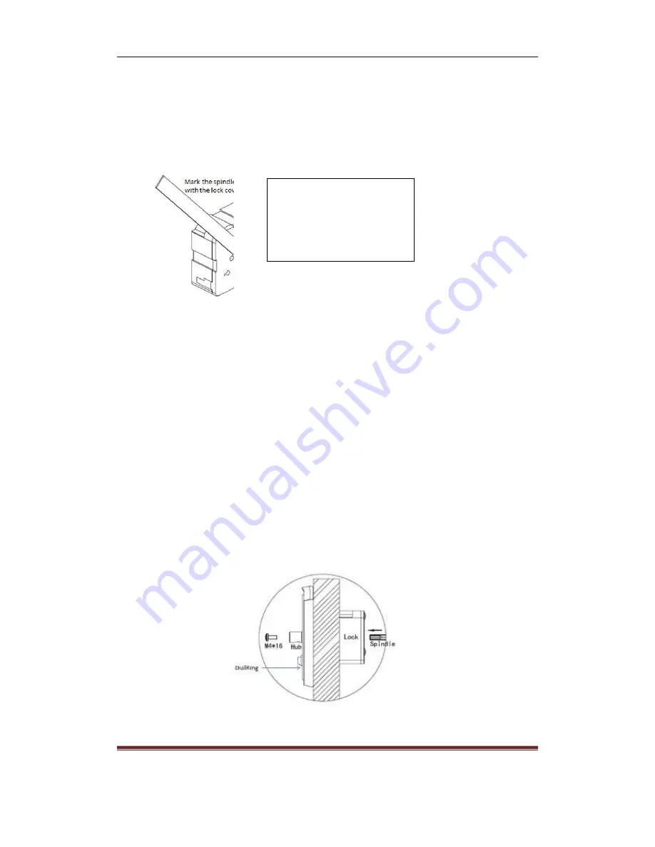
Step 9: Mark the spindle length flush to the lock cover.
The length of the spindle can be
precut to a length equal to Door
Thickness (DT) + 1.75”
Step 10: Remove the spindle bolt (Part# M4*16) and spindle (Part# MSP-15A-6IN) from lock case
prior to cutting. Carefully cut the spindle so that it will be flush to the lock cover.
Step 11: Remove all burrs from the spindle using a file.
Step 12: Now insert the Spindle (drilled and tapped end first) into the spindle insertion point and
through the clear plastic tube. Ensure that the cable is held taught while inserting the
spindle so that it does not become damaged.
Step 13: Continue to push the spindle into place until it reaches the DialRing hub.
Step 14: At the DialRing, insert the M4*16 spindle screw into the DialRing hub and tighten. Now
tighten the Lock Mounting Bolts (QTY: 3)


