4. INSTALLATION
4.1.
Always ensure that components are installed in the air line in the correct flow direction. The flow direction is cast into the top casing of
each unit.
4.2.
Install the filter (if separate) upstream from the regulator and the lubricator downstream from it.
4.3.
To install SA2001.V2 fix the integral mounting bracket to the wall.
4.4.
To mount the SA2001/FR.V2 filter regulator and SA2001R regulator fix the mounting bracket provided to the wall. Remove the mounting
bezel (fig.1.8) from the neck. Place the neck through the mounting bracket and replace the bezel to clamp the mounting bracket.
4.5.
To install the pressure gauge (fig.1.2.), remove the blanking plug and screw in the gauge. PTFE tape may be required to achieve a good
seal.
4.6.
The SA2001/F.V2 and SA2001/L.V2 can be installed in the pipe run, supported by the pipe. Ensure pipe is adequately supported.
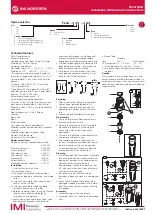
Key to fig.1:
1 Pressure Adjustment Knob
2 Pressure Gauge
3 Filter Drain
4 Bowl Release Catch
5 Oil Filler Plug
6 Oil Feed Sight Glass
7 Oil Feed Adjustment
8 Mounting Bezel
9 Mounting Bracket
fig.1
5. OPERATION
6. ADDITIONAL FITTINGS
5.1.
Regulator
- The output pressure is controlled by the pressure adjustment knob (fig.1.1). Before pressurising air system for the first time lift
and rotate knob anticlockwise to remove any loading on the regulator spring. Pressurise the system and then rotate knob clockwise to set
the required output pressure, as shown on gauge (fig.1.2). When the required pressure is achieved lock knob by pushing down.
Note: For correct pressure setting always adjust upwards from a lower pressure. Therefore to reset from 90 to 70psi, for example, reduce
pressure from 90 to 60psi and then increase from 60 to 70psi.
5.2.
Filter
- The bowl will drain automatically each time the system pressure drops to zero. However; if the fluid level reaches the maximum
mark but the system is to remain pressurised the bowl can be manually drained by pushing the filter drain (fig.1.3) upward.
Note: the drain is designed to take a flexible tube so that the waste fluid can be piped away.
5.3.
Lubricator
- Remove filler plug (fig.1.5) and fill bowl with air tool oil. This can be done with air line pressurised.
With air flowing through the lubricator the oil delivery rate can be adjusted by means of the oil feed adjustment (fig.1.7) whilst watching
the feed rate through the sight glass (fig.1.6). The oil delivery rate will be increased or decreased automatically in line with the air flow.
The following fittings are available from your Sealey supplier:
SA1/1414
..............................1/4”BSP-1/4”BSP male-male nipple
SA1/1212
..............................1/2”BSP-1/2”BSP male-male nipple
SA1/3814F
.........................3/8”BSP-1/4”BSP male-female reducer
SA1/1214F
............................1/2”BSP-1/4”BSP male-female reducer
SA1/1238F
............................1/2”BSP-3/8”BSP male-female reducer
Environmental Protection
Recycle unwanted materials instead of disposing of them as waste. All tools, accessories and packaging should be sorted, taken to
a recycling centre and disposed of in a manner which is compatible with the environment. When the product becomes completely
unserviceable dispose of it according to local regulations.
NOTE:
It is our policy to improve products continually and as such we reserve the right to alter data, specifications and component parts without
prior notice.
IMPORTANT:
No liability is accepted for incorrect use of this product.
WARRANTY:
Guarantee is 12 months from purchase date, proof of which will be required for any claim.
01284 757500
01284 703534
Sole UK Distributor, Sealey Group,
Kempson Way, Suffolk Business Park
,
Bury St. Edmunds, Suffolk,
IP32 7AR
www.sealey.co.uk
© Jack Sealey Limited
Original Language Version
SA2001.V2,SA2001/F.V2, Issue:2 - 08/11/16
SA2001/FR.V2,SA2001/L.V2, SA2001R