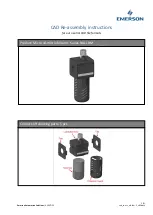
JDS Uniphase TB9 Series, User Manual
The JDS Uniphase TB9 Series User Manual is a comprehensive guide to effectively operating and maintaining your TB9 device. Download this manual for free from our website to access detailed instructions, troubleshooting tips, and expert advice, ensuring optimum performance and longevity for your product.
Share
Download


Reviews:
No comments
Related manuals for TB9 Series

LF919
Brand: Watts Pages: 12

MCE 600
Brand: Deltec Pages: 7

Star Pulsar ESFR-1
Brand: Tyco Fire Product Pages: 4

EWS 6
Brand: A.O. Smith Pages: 16

EuroPEK Filter
Brand: Wavin-Labko Pages: 11

ROFK5
Brand: Abundant Flow Water Systems Pages: 20

MTS 5000 UV 7
Brand: T.I.P. Pages: 56
NL4-LBM Series
Brand: Emerson Pages: 3
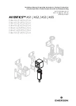
AVENTICS AS1
Brand: Emerson Pages: 47

FC4C
Brand: LAMA Pages: 24

VC722VC120
Brand: Ryobi Pages: 2

COMPAC Series
Brand: AOX Pages: 4

RS-103TDS
Brand: PurePro Pages: 8

5908607850
Brand: Scheppach Pages: 108

Easy Arm Extraction EA 110 plus i
Brand: ersa Pages: 8

Rettin UCE Series
Brand: Tyent Pages: 28

Body Glove BG-12000
Brand: Water Pages: 8

PuriFIRE VERSA SEA PAK 200
Brand: DARLEY Pages: 36


