

F64G Filter
Installation & Maintenance Instructions
6/15
I&M/en 8.240.100.01
Our policy is one of continued research and development. We therefore reserve the right to amend,
without notice, the specifications given in this document. (1999 - I&M8074d) © 2015 IMI International s.r.o.
Fluid: Compressed air
Maximum pressure:
Guarded transparent bowl: 10 bar (150 psig)
Metal bowl: 17 bar (250 psig)
Operating temperature*:
Transparent bowl: –20° ... +50°C (0° ... +125°F)
Metal bowl: –20° ... +80°C (0° ... +175°F)
* Air supply must be dry enough to avoid ice
formation at temperatures below +2°C (+35°F).
Particle removal: 5 µm, 25 µm or 40 µm filter
element
Air quality: Within ISO 8573-1, Class 3 and
Class 5 (particulates)
Typical flow with 40 µm element, 6,3 bar (90
psig) inlet pressure and 0,5 bar (7 psig) droop
from set: 70 dm
3
/s (148 scfm)
Automatic drain connection: 1/8”
Automatic drain operating conditions:
Pressure: 0,7 bar (10 psig). Drain opens when
bowl pressure drops below 0,2 bar (3 psig).
Minimum air flow: 1 dm
3
/s (2 scfm) required to
close drain
Nominal bowl size: 0,2 litre (7 fluid oz)
Materials:
Body: Zinc
Bowl:
Metal: Aluminium
Transparent, optional: Polycarbonate
Metal bowl liquid level indicator lens, standard:
Grilamid
Metal bowl sight glass, optional: Pyrex
Element: Sintered plastic
Elastomers: Synthetic rubber
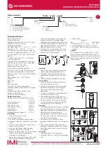
Replacement Items
Service kit, contains required items circled:
4380-200
Prismatic sight glass
4380-040
Pyrex sight glass
4380-041
Filter element, 5 µm
4338-01
Filter element, 40 µm
4338-02
Manual drain
684-84
Automatic drain
3000-97
Mechanical service Indicator (1) 5797-50
Installation
1. Install unit vertically in air line -
• vertically (bowl down),
• with air flow in direction of arrow on body,
• upstream of regulators, lubricators, and cycling
valves,
• as close as possible to the air supply when
used as a main line filter,
• as close as possible to the device being
serviced when used as a final filter.
2. Before assembling the basic unit into the yoke
the port seal o-rings should be lightly
smeared with o-ring grease.
3. Locate clamp ring under lugs on top of yoke,
offer basic unit into yoke with directional
arrows correctly aligned (an interference fit
prevents assembly if misaligned) before
engaging and fully tightening the clamp ring.
4. Turn bowl or bowl guard fully clockwise into
body before pressurizing. Lock symbols on
body and bowl guards must align.
5. Auto-drain units may be fitted with a short
drain pipe and connector, minimum 5 mm
bore, to the G1⁄8 bottom outlet.
A
B
C
Servicing
1. Open manual drain to expel accumulated
liquids. Keep liquids below baffle (53).
2. To operate automatic drain manually, lift
operating pin in bottom outlet with a blunt
rod.
3. Clean or replace filter element when dirty.
Disassembly
1. Shut off inlet pressure. Reduce pressure in
inlet and outlet lines to zero.
2. For ease of maintenance the unit can be re
moved from the yoke by unscrewing the
clamp ring, which will jack the unit out
downwards.
3. Lift and turn the filter bow counterclockwise
and remove with bowl o-ring.
4. Disassemble in general accordance with
the item numbers on exploded view. Do not
remove the drains or the service indicator
unless replacement is necessary. Remove
and replace only if they malfunction.
Cleaning
1. Partial cleaning of the filter element is possible
by washing the element in soapy water and
blowing out thoroughly with compressed air.
Replacement by a clean element is
recommended. Clean plastic bowl and lens
(45) with warm water only. Clean other parts
with warm water and soap.
2. Rinse and dry parts. Blow out internal
passages in body with clean, dry compressed
air.
3. Inspect parts. Replace those found to be
damaged. Replace plastic bowl with a metal
bowl if plastic bowl shows signs of cracking
or cloudiness.
Assembly
1. Lubricate o-rings with o-ring grease.
2. Assemble the unit as shown on the exploded
view.
3. Torque Table
Torque in
Item
N-m
(Inch-Pounds)
55 (Filter guide) 2,0 ... 2,7 max
(18 ... 25)
4. Assemble baffle (53), c 1/4 turn.
5. Turn bowl or bowl with guard fully clockwise
into body.
Caution
Water vapor will pass through these units and
could condense into liquid form downstream as
air temperature drops. Install an air dryer if water
condensation could have a detrimental effect on
the application.
Technical features
Option selector
Port
2 1/4”
3 3/8“
4 1/2“
6 3/4
Option
D
Service indicator
N None
Bowl
D Metal
P
Transparent with guard
R
Metal with Pyrex sight glass
Element
1
5 µm
2
25 µm
3
40 µm
Thread
A
PTF (1/8 PTF gauge ports)
B
ISO Rc taper (1/8 ISO Rc gauge ports)
G
ISO G parallel (1/8 ISO Rc gauge ports)
N
No thread (basic unit)
F64G –
˙˙˙
–
˙˙˙
Drain
A Automatic
M Manual
Q Manual 1/4 turn
55
56
8
7
6
2
4
3
5
1
48
32
47
18
31
30
29
43
44
46
45
40
36
38
37
41
42
39
33
35
34
26
22
24
23
27
28
25
19
21
20
54
53


