1. Set the temperature, the time, the slope and so on parameters of the
upper heater;
2. Adjustment process proposed to do on a waste circuit board in order to
prevent damage to the circuit board and on-board electronic
components.
3. Implementation of the above process (3), installed the external
thermocouple, in which the top of the PCB board just below the hot-air
tube.
4. Close the lower part of the heating process, click on "Start" button to
start the heating process, which will on the computer monitor screen
will be displayed on the upper curve of the measured temperature
(green) and external galvanic measuring temperature (red) the two
curves;
5. Green curves represent the actual measurement of the galvanic
temperature curve of the upper heating wire interior, the red curve
represents the actual measurement of the galvanic temperature
outside. the smaller the gap between the green curve and red curve,
the closer between the actual temperature and set temperature of the
heating parts, more standard of the upper heating process; On the
contrary, the greater the gap between the two curves, the greater the
actual temperature deviate from the set temperature, the more
non-standard of the upper part during the heating process.
6. If the deviation between the two curves is too much, you should make
the appropriate adjustments.
7. The specific adjustment method is as follows, because of the impact of
the system processes and the environmental, deviations in the
objective is inevitable. If the temperature deviation does not affect the
normal welding and de-soldering, non-professionals should avoid the
following corrective actions!
A. If the outer galvanic curve (red) lower than the upper one (green), adjust
the internal hairdryer galvanic probe upward;
B. If the outer galvanic curve (red) higher than the upper one (green),
adjust the internal hairdryer galvanic probe downward;
C. Adjustment must be small, try to control the amplitude of
accommodation in 1mm or less;
Содержание ACHI-HR15000
Страница 1: ...ACHI HR15000 Rework Station NO ACHI HR 15000 Instruction Manual Shenzhen Scotle Technology Co Ltd...
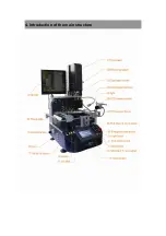
Страница 6: ...4 Introduction of the main structure...
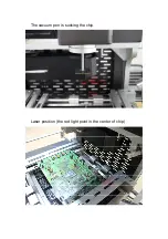
Страница 24: ...The vacuum pen is sucking the chip Laser position the red light point in the center of chip...
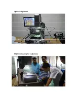
Страница 25: ...Optical alignment Machine testing for customers...
Страница 26: ......

