background image

10 


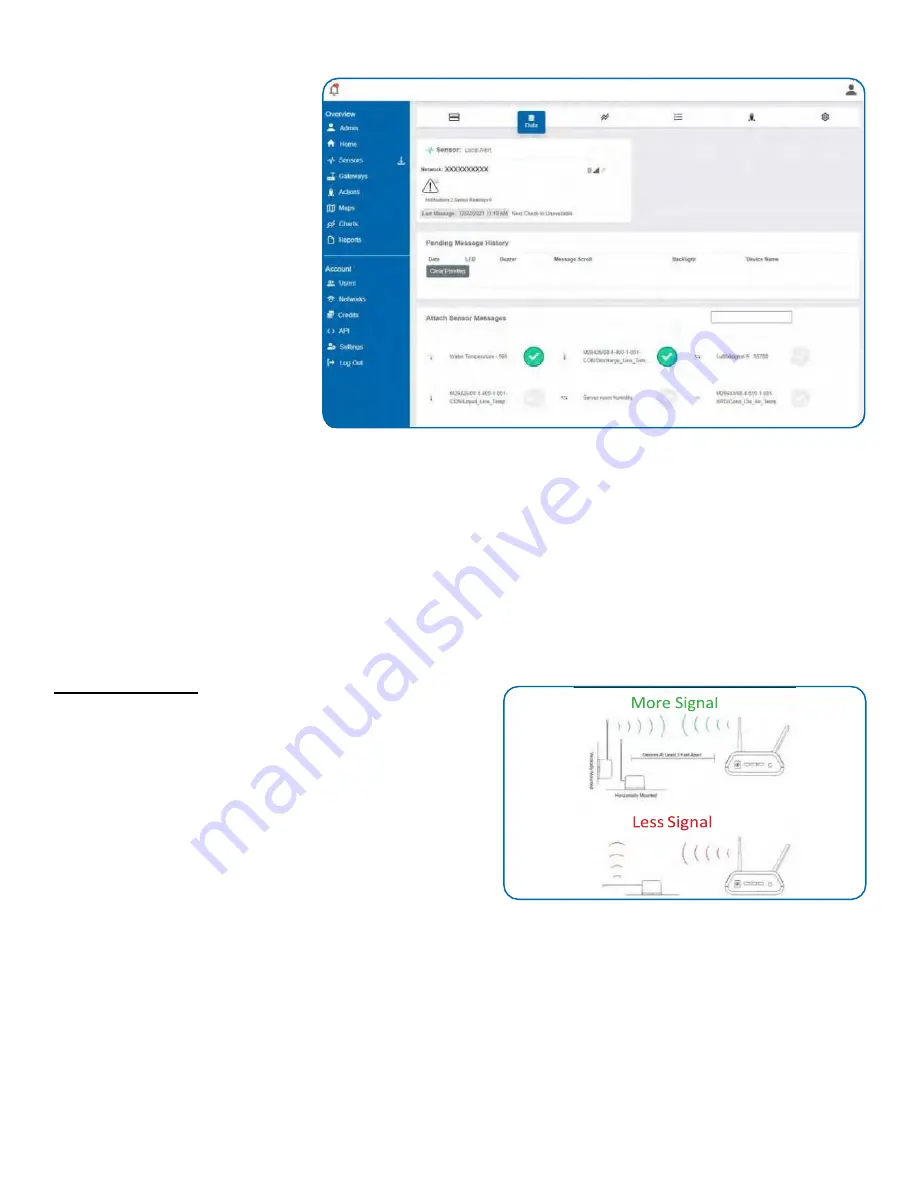
STEP 6: SENSOR READINGS FOR LOCAL ALERT 

1. Select the 

Local Alert

 device in the 

Overview

 screen. 

2. Go to the 

Data

 tab. 

3. Add sensors using the 

Attach 

Sensor Messages

 screen. 

Note: Pending Message History


displays all notifications and sensor 
readings that have not yet been 
received by the Local Alert. The 

Clear 

Pending

 button will clear everything 

in the 

Pending Message History

 list. 


POWERING THE LOCAL ALERT ON AND INSTALLING THE ANTENNA 

Attach Antenna 

In order for the Local Alert to function properly, you will need to attach the included antenna. Simply screw the antenna 
onto the barrel connector on the side of the device. Make sure the antenna connection is snug, but do not overtighten. 
Refer to Antenna Orientation guide below for best radio performance. 

Powering On the Local Alert 

Insert batteries and/or line power and slide the switch on left side to the "On" position. 

Antenna Orientation 

In order to get the best performance out of your GEN 2 device, it 
is important to note proper antenna orientation and device 
positioning. Radio performance is best when device and gateway 
antenna are pointing in the same direction and installed on the 
same plane. For devices installed on the same horizontal plane 
this means the antenna should be pointed straight up. If devices 
are installed on the same vertical plane antenna should be 
aligned on the same horizontal plane and still pointing in the 
same direction. 


Resetting Sensor 

If the sensor needs to be reset for any reason, you can simply cycle the power by toggling the switch to the "Off' position 
and waiting 30 seconds before powering back on. Holding the tactile button for 10+ seconds will also cause a reset. 

Storage 

Always set the power switch to the "Off" before storing the Local Alert to preserve battery life. 


Содержание RFR-0541-2

Страница 1: ...1 GEN 2 Wireless Local Alert RFR 0541 2 User Guide IMPORTANT Powering off the Local Alert will delete any saved notifications or sensor readings however any configuration changes will be saved...

Страница 2: ...G NETWORK 6 III SET UP IN SCIGIENE PREMIER 7 ADD DEVICE 7 SET UP 7 VALIDATION 8 ACTIONS 8 NOTIFICATIONS 9 SENSOR READINGS 10 IV LOCAL ALERT OVERVIEW IN SCIGIENE PREMIER 11 MENU SYSTEM 11 DETAILS VIEW...

Страница 3: ...GEN 2 WIRELESS LOCAL ALERT QUICK START 1 Create an Scigiene Premier user account 2 Add wireless gateway s and sensor s to the network 3 Add the Local Alert device to the sensor network 4 Power on the...

Страница 4: ...sages The left number indicates the current message being displayed The right number indicates how many total messages are on the Local Alert 9 Signal Strength This icon indicates the signal strength...

Страница 5: ...be received locally where someone is most capable of responding to a critical condition The Local Alert displays notifications and sensor messages Notifications are messages generated by Scigiene Pre...

Страница 6: ...dix A for more detailed information on the Local Alert s behaviors II ORDER OF OPERATIONS It s important to understand and follow the order of operations for activating the GEN 2 Local Alert If perfor...

Страница 7: ...to add a sensor These can both be located on the label on the side of your device 3 Adding your device You will need to enter the Device ID and the Security Code from your sensor in the corresponding...

Страница 8: ...and to speed up this process 3 Make sure Local Alert is powered Attach the included antenna and switch on the Local Alert see the Powering Sensor On and Attach Antenna sections for help in this area O...

Страница 9: ...the notification Click the icons next to the selected Local Alert to activate deactivate different alarms Click the right arrow button to advance to the sensor selection screen The message sent to the...

Страница 10: ...lert Insert batteries and or line power and slide the switch on left side to the On position Antenna Orientation In order to get the best performance out of your GEN 2 device it is important to note p...

Страница 11: ...corner of the sensor icon denotes its status Green indicates the Local Alert is checking in and within user defined safe parameters Red indicates the Local Alert has met or exceeded a user defined th...

Страница 12: ...ng information about the state of the Local Alert when the message was transmitted See Sensor State explained below Alert Sent Boolean indicating if this reading triggered a notification to be sent fr...

Страница 13: ...On state before scrolling to the next message K Time Zone Offset Sets the time on the Local Alert to the same time zone as the Scigiene Premier account L LCD Contrast Increasing LCD contrast will dark...

Страница 14: ...grade security at every DATA SECURITY ON THE GATEWAY GEN 2 Gateways are designed to prevent prying eyes from accessing the data that is stored on the sensors and Local Alert devices Gateways do not r...

Страница 15: ...cation was generated in Scigiene Premier 1 Check the Heartbeat on the gateway that the Local Alert is connected to in Scigiene Premier The notification must get to the gateway before being sent to the...

Страница 16: ...orking contact Scigiene Support 3 The Local Alert can be powered from battery and or line power When on battery only a battery icon will appear in the status bar at the top of the display If this icon...

Страница 17: ...hirty seconds of viewing a notification reading without any user interaction thebacklight willturn offautomatically Pressing the button at this point will turn it back on Button Pressing the button wh...

Страница 18: ...18 VIII LOCAL ALERT BEHAVIORAL FLOW DIAGRAM...

Страница 19: ...ithout backlight LED One Ultra Bright Red LED 1630 mcd 110 x 45 Viewing Angle Buzzer 85 dB 30 cm 2 5 KHz 500 Hz Enclosure ABS plastic Dimensions 4 0 x 4 0 x 1 6 in 101 6 x 101 6 x 40 64 mm Excluding a...

Страница 20: ...validRMA number provided byScigiene Customer acknowledges that replacement products may be repaired refurbished or tested and found to be complying Customer shall bear the risk of loss for such retur...

Страница 21: ...radio transmitter IC 9794A RFSC1 has been approved by Industry Canada to operate with the antenna types listed on previous page with the maximum permissible gain and required antenna impedance for ea...

Отзывы: