


Date Code 980420
Operation Within SEL-2030
4-21
SEL-2711 Instruction Manual
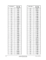
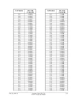
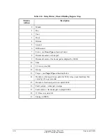
Table 4.3: Input Register Map
Input Register
Offset Address
User Region
1 - 2048
Port 1 User Region
2049 - 4096
Port 2 User Region
4097 - 6144
Port 3 User Region
6145 - 8192
Port 4 User Region
8193 - 10,240
Port 5 User Region
10,241 - 12,288
Port 6 User Region
12,289 - 14,336
Port 7 User Region
14,337 - 16,384
Port 8 User Region
16,385 - 18,432
Port 9 User Region
18,433 - 20,480
Port 10 User Region
20,481 - 22,528
Port 11 User Region
22,529 - 24,576
Port 12 User Region
24,577 - 26,624
Port 13 User Region
26,625 - 28,672
Port 14 User Region
28,673 - 30,720
Port 15 User Region
30,721 - 32,768
Port 16 User Region
32,769 - 34,816
Port 17 User Region
34,817 - 36,864
Port 18 User Region
The addresses shown in this table are one greater than those passed in the actual Modbus
messages.
To determine the specific input register offset address of a specific User Region register, add the
User Region offset address to the beginning input register for that port. For example, if you want
to access register F932h on Port 13, first subtract the User Region base address to determine a
offset value:
F932h - F800h = 132h = 306.
Then add this to the beginning address for the Port 13 input registers:
306 + 24,577 =
24,813
.
H
OLDING
R
EGISTER
D
ATA
M
APPING
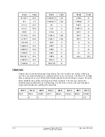
Holding registers can be mapped one of two ways, based on the MAP_IR setting. If this is set to
yes, the map will be identical to that listed in the previous section, except that to determine normal
4x references, you will need to add 40000 to the values given in the table. If the MAP_IR setting
is set to N, then the map will be as described below.
The holding register map is broken into two main segments. The first 10000 registers (those
accessible using 4x references) are broken into 500 register blocks with data from each port in an
appropriate block. The second segment consists of 36,864 registers which correspond to the User
Regions of all 18 ports.