


4-12
Operation Within SEL-2030
Date Code 980420
SEL-2711 Instruction Manual
(continued from previous page)
B 20METER
B 20TARGET
A 20HISTORY
A 20STATUS
A 20EVENT
A 20EVENTS
A 20EVENTL
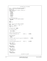
Port 2:
Warning: Current device does not support some Automatic Message settings
Automatic Message settings not supported by the new device were lost
Port 2 Settings Changed
**>>
COPY 1 3<ENTER>
COPY 1 3<ENTER>
Copy settings from Port 1 to Port 3 (Y/N) ?
Y<ENTER>
Y<ENTER>
Perform auto-configuration on Port 3 (Y/N) ?
Y<ENTER>
Y<ENTER>
Attempting auto-configuration...Done.
FID: FID=SEL-351-R101-VM-D970616
DEVICE ID: FEEDER 1
BAUD RATE: 2400
OPERATE SUPPORT: Binary (1 Breakers, 8 Remote Bits S-C-P)
COMMANDS SUPPORTED:
B 20METER
B 20DEMAND
B 20TARGET
A 20HISTORY
A 20STATUS
A 20EVENT
A 20EVENTS
A 20EVENTL
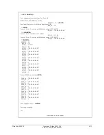
Port 3 Settings Changed
**>>
Once the three relay ports are set up to collect data, we can extract this data using Modbus Plus.
Simply connect a Modbus Plus master to the SEL-2711 and begin collecting data using the data
maps provided later in this section. We can now also control the breakers by operating on RB1 on
each of the relay ports.
C
ONFIGURING
SEL-2711 P
ORT
On the SEL-2711 port, we can define global data to be transmitted, monitor for incoming global
data, and create control operations to issue to other nodes on the network.
To configure global data to be sent on the network, use the SET M command on the SEL-2711
port (Port 17 or 18). The first 32 registers used in the User Region will be sent onto the network
as Global Data. The first 500 registers of the User Region are also visible as the final 500 holding
registers in the standard holding register map.
Global data from other nodes on the network are automatically placed in region D1 on the
SEL-2711 port. The first 32 registers are the global data from node 1, the next 32 are from 2,…